9. REFRESHING A LIEGE MADE "GERARD" TYPE REVOLVER
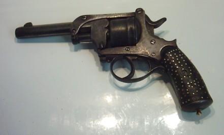
One of our members hands me a very strange revolver made at Liège, of a model I never had seen before except on pictures. According to the owner, the revolver is of a type patented by Gerard, a Liège gunmaker who invented its system.
The gun is worn and dirty, and its lock mechanism doesn't work very well.
Before starting to work on it, however, I made some research and found on the gun the logo of Jules Kaufmann, another Liège gunmaker, who manufactured and distributed that model.
The gun should be a military model, often called "Brazilian Model"; according to one of our contacts, it has effectively seen service in the Brazilian army during the 1880's.
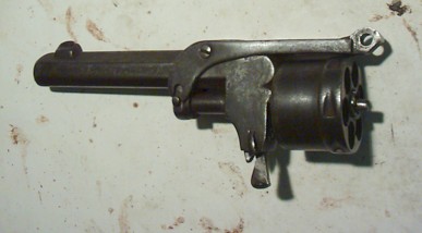
IDENTIFICATION
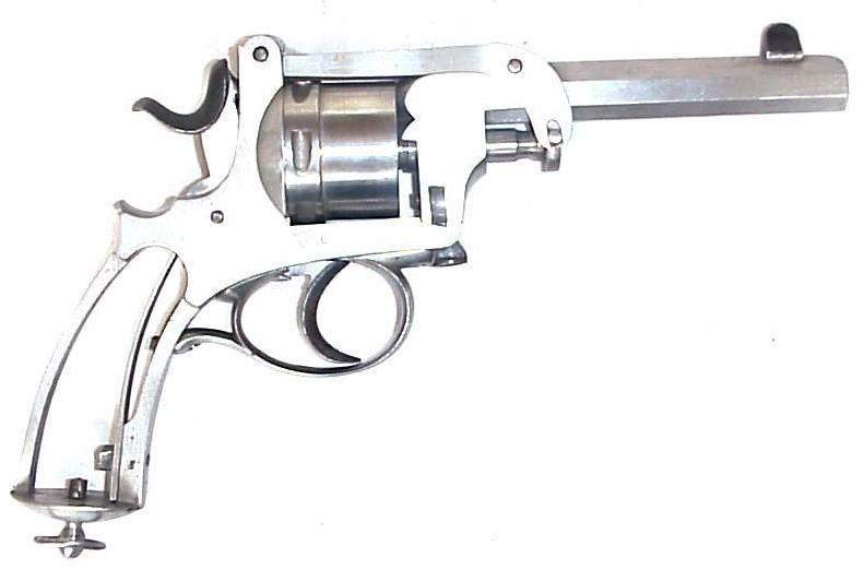
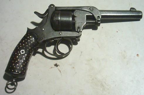
- Double and single action, .380 caliber (9 mm) central fire revolver
- 6 rounds cylinder
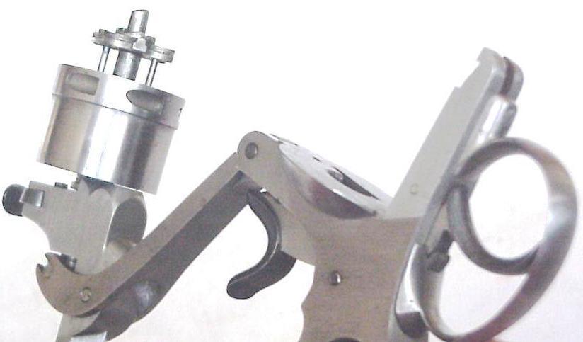
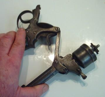
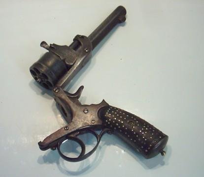
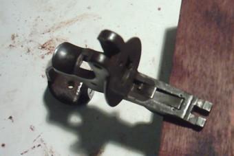
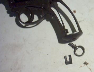
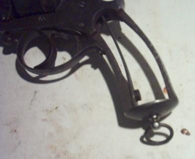
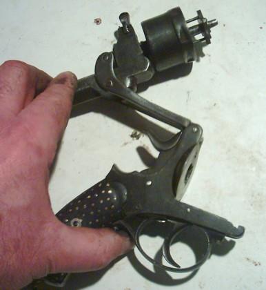
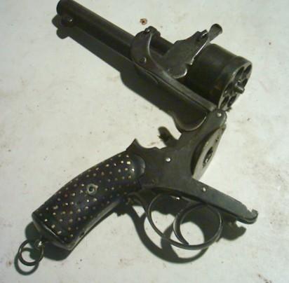
- The frame opens by pressing a button located ahead of the cylinder; the barrel tips up completely.
A toggle is mounted on the barrel, of which the rear part is maintained by a screw at the barrel hinge, while the forepart shoves alongside the barrel during the opening movement. When the barrel is completely tipped up, the front part of the toggle pushes on the cylinder axis head, which causes the star extractor to come out and eject the empty shells. Pushing a little bit more causes the star ejector to come back in its closed position, enabling for reloading.
This ejection system is actually a variant to that used on the American Smith & Wesson 3rd model and the British Webley revolvers that were very popular in those days, especially among horsemen.
The Gerard shows a system that is more complicated, without being any better, since the ejection and reloading operations are not faster, while the various pressures on the numerous hinges and axes tend evidently to cause premature wear which causes the weapon to shatter apart and renders it useless.
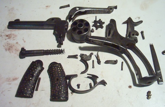
Moreover, the large amounts of component parts make it an expensive gun to make - allow me to criticize - which is normally not popular among military buyers.
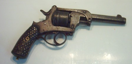
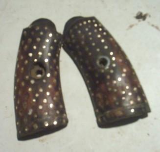
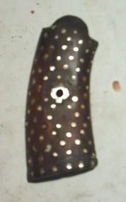
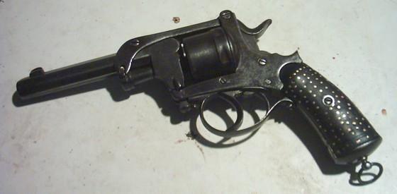
- Walnut grips (plain or chequered?), imitating ebony. The grips on this one are the original ones, since them bear the same number as all other component parts; but a formal owner has "customed" them with a great number of copper nails that are not very well aligned.
- Time and dirt have given the gun a black patina; but a light cleaning with petroleum seems to confirm that it was originally white polished. I can't find any trace of bluing on it.
This gun is identical to the unfinished one owned by the Liège Museum of Arms
MARKINGS
- On every part including the grips: # 680
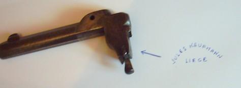
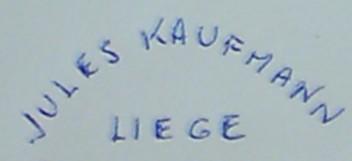
- On the left side of the frame, ahead of the cylinder: the name JULES KAUFMANN in a half circle, and the word LIEGE stamped horizontally within the circle (see pictures 8 and 9)
- On the internal side of the barrel lug, around the breech, is a serial of very tiny letters or numbers that I can't read; then the initial M written in cursive with a large crown above it.
- There are no Liège proof stamps, nor controller's initials. Those stamps could have been erased by a formal polishing, but I doubt it. More probably, the maker chose
to spare costs by avoiding the proof, since the guns were intended for export. A formal polishing would have erased the other markings as well.
CLOSE EXAMINATION AND DIAGNOSTICS
This weapon has evidently seen intensive use. There is no trace of rust or pitting whatsoever, but there are numerous other flaws:
- Heavy wear on all hinges and on the opening button: the gun almost shatters apart
- Trigger return spring missing
- The hammer does not rebound anymore
- The extractor doesn't work properly
- The swivel ring has been lost and replaced by a crudely made copper pin
- The original screw to the main spring has been replaced by another one, that doesn't fit
- Grip plates worn, damaged and naively decorated with copper nails. The screw is worn beyond any hope
- Thick layer of dirt all over.
REPAIRS TO BE DONE
The job is to give the gun a better look and to make it work normally. However, a complete restoration is out of the question; so I will make a new return spring to the trigger, make the lock mechanism work again, and clean the gun, and that's all.
Regarding the grips, I intend to repair the damaged screw hole, file the copper nails to the wood level and polish again. As they are original, I think it is better to keep them instead of replacing them by copies. The only part that needs to be replaced is the screw, for it is completely worn.
DISASSEMBLING
Right from the beginning, I can see that the main spring will be a source of problems. It is a flat spring with a fork at its upper part, hold to the forepart of the grip frame
by a screw. On this revolver, the original screw has been replaced by a modern one that has been flattened on both sides of the frame, so that it is like a rivet and is absolutely impossible to unscrew.
However, I need to remove the spring if I want to disassemble the rest of the gun and assemble it again afterwards.
I can't cut the screw with a torch, for the heat would distemper the spring; and I can't use a chisel either, for I could break the spring or damage the grip frame.
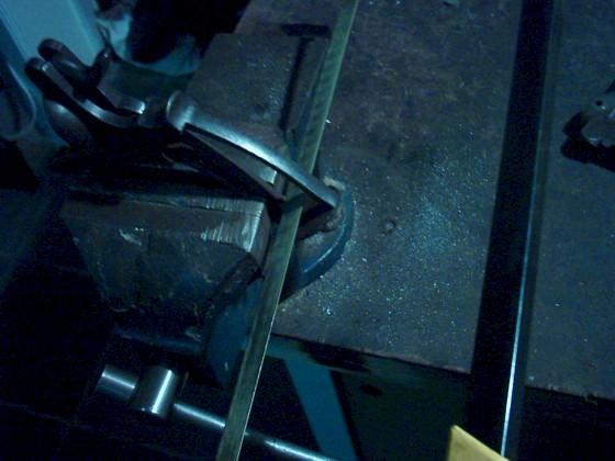
So I've got but one possibility: holding the frame in my vice, I introduce my metal saw in the middle of it and I make a new cut into what is left of the screw head.
Then on the outside I file the end of the screw flush with the grip frame; then I give the whole thing a drip of penetrating oil, which I allow to work for a while.
Using a large screwdriver, I make a first attempt to unscrew the screw. It moves slightly, but finally I need to use a small punch to drive that bloody screw out.
Finally I can extract it, and I am glad to see that both the spring and the original threads in the hole are intact.
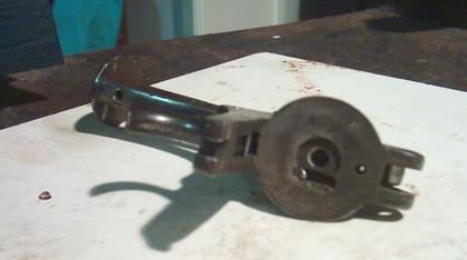
Once the spring removed, I can disassemble the rest of the gun very easily (picture 10).
CYLINDER RETAINING CLAW
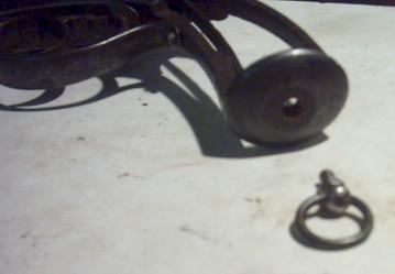
Pictures 8 and 9 show the rear face of the barrel lug, with the enveloping claw that is meant to keep the cylinder in place when the extractor is pushed out. The cylinder has a thick edge on its front face, around its axis hole, that engages the claw.
Because of heavy wear, the claw fails to retain the cylinder.
The only thing I can do is trying to reduce the effects of wear, which I do by heating the barrel lug and make the claw fit tighter by tapping it with a hammer. I can't heat too hot, otherwise I would soften the metal; I just need to make it soft enough to be bent without breaking.
The treatment proves to be working, as I can state by reassembling the cylinder on the barrel lug and activating the mechanism by hand.
Meanwhile I have cleaned the Jules Kaufmann logo on the left side of the frame
TRIGGER RETURN SPRING
As it often happens, the trigger return spring has been lost, and has been replaced by another one, that is not only incorrectly bent, but also bad tempered. It is totally useless.
As I usually do, I cut a V spring to the right shape in a piece of untempered spring steel; I heat it cherry red, and when the metal starts making sparks, I temper it hard by throwing it in cold water.
Then I polish it to get the metal white again, and I soften it back in oil: having placed it on a metal thimble on my small oven, I let it heat slowly until it gets a dark matt blue color; then I take it away from the fire and throw it in a cup of engine oil. Once cooled, it proves to be strong and elastic, and all I have to do is mounting it in place in the frame.
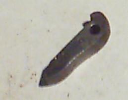
HAMMER REBOUND LEVER
The hammer rebound lever - that short lever that is mounted beyond and beneath the trigger - is worn so far that it has no effect anymore. I could of course make a new one, but I decide to keep the original one because it also bears the # 680 like all the other component parts of the gun. The problem is that wear has shortened it, so that its forepart lost almost any contact with the rear curve of the trigger block.
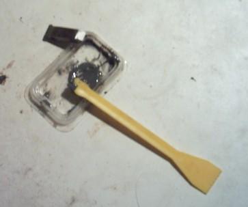
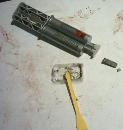
In order to solve that little problem, I'm going to glue a small piece of metal as an inlet on the head of the lever, so that its length would increase about 1/2 millimeter.
I cut a small part of coil steel, and glue it on the head of the rebound lever by means of a 2-components epoxy glue.
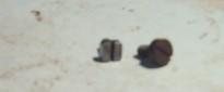
MAIN SPRING SCREW
This is easy. I found in my stock a good clockmaker's screw, contemporary to the gun and with the same old British threads. I file its head into a square, as is often found on Liège-made revolvers of the time. The square head allows for better and easier tightening with a wrench rather than a screwdriver, since it is impossible to hold the screwdriver straight due to the smallest of the grip frame. I temper my screw to make it harder.
REASSEMBLING THE LOCK MECHANISM
Once the glue has hardened, I can reassemble the whole lock mechanism. There is no problem whatsoever with the main spring, but I can see that the repaired rebound lever still does not push the hammer as far as it originally did. It holds the hammer back just far enough to enable the firing pin to hide in the percussion channel, but extreme wear around its axis makes a true rebound impossible.
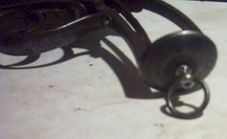
SWIVEL RING
Here I got no choice. The original swivel ring has been lost and replaced by a copper pin that comes from God knows where.
I take that copper pin out; it should be replaced by a swivel ring that can be turned into all positions.
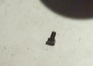
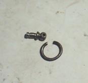
I first make a new pin, featuring a rounded head with a hole in it. I can easily make that part out of a large size carpenter nail, hold into the mandrel of my electric drilling machine. While it is turning I give it the right shape using a small hard file. It is quite easy to file into the right shape, being a round ball with a "shoulder" to rest against the pinhole.
At the inner side I have to cut a narrow groove into the pin, making sure that it comes right above the frame level at the inside. That groove is meant to take a small U-shaped spring that will hold the pin in place but allow it to turn 360° around its axis.
To make the ring itself, I simply cut one spiral out of an old spiral spring, and soften it in order to bend it into the right shape.
Then I simply push both ends of my ring into the hole in the pin's head, and close the ring with pincers. That's it; the only thing I got to do now is temper the whole part again.
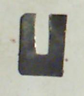
Now I cut a small U-shaped flat spring out of a large clock spiral spring; I cut it just so that it fits tight into the groove I cut in the pin, so it holds it firmly in place but allows it to turn. The spring itself is just long enough to rest against the grip plate, so that it can't slip away when the gun is assembled.
REPAIRING THE GRIPS
As said in the beginning of this article, the grips on this revolver have been "personalized" with several small copper nails, evidently punched in by an amateur who either wished to imitate what he had seen on some luxury weapons, or simply intended to personalize his gun.
No need to say that there is any way to extract those nails without damaging the grips wood.
However, the nail heads are protruding, which makes the grips unpleasant to hold, while it gives them a rather neglected look. Since I can't either take the risk of punching them further in without the risk of cleaving the wood, I decide to simply file them to the level of the wood surface, using a file and sand paper.
Since the wood appears to be weak, however, I will avoid taking risks and will not file too deep.
I honestly think that the treatment has given a better look to the grips.
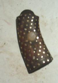
The right grip is damaged around the escutcheon: the wood is fragmented and damaged around the hole, and the screw itself is totally rusted and rotten. I'll have to make a new one, which can be done quite easily using a modern screw of the same diameter.
To repair the damaged hole in the grip, I start by drilling it gently with a hand drill, in order to obtain a larger hole with nice round edges. Then I introduce a wooden cylinder in it, which I have cut out of a piece of walnut, respecting the wood fibers (picture 31). I make that wooden cylinder long enough to fill the hole through all the way through the thickness of the grip. It is also thick enough to fit tightly in place. I put a drip or two of wood glue in the hole, and then I push the wooden cylinder home in the hole.
Once the glue has dried, I file the inlet rise with the grip using sand paper.
Now I need to drill a new hole for the screw, which I do with a hand drill. Holding both grips in place on the frame, I introduce my drill through the hole in the left one, so that I can drill my hole from the inside at the exact location.
When the hole is drilled, I first give the escutcheon a better shape by filing it a little. It is a home made copper escutcheon, featuring two lateral protuberances.
Using a larger hand drill, I mill the external side of the hole a little bit larger, and cut two recesses for the escutcheon to fit. Then I push the escutcheon home, glued with a drip of varnish to hold it firmly in place. This has to be done carefully. The hole should not be made too large, so that the escutcheon can fit tightly into it. Not too narrow either, for the pressure could break the grip when it is pushed in (picture 35).
REASSEMBLING THE GUN
Now the repairs have been done, and all I need to do is reassemble the whole gun.
I failed to reduce the wear to zero in the numerous hinges and the gun is still a bit loose, yet I think I may say it has now a better general look.
Anyway, both the lock mechanism and the ejector work normally again, and that is the most important point.
Even in its worn condition, that scarce revolver is still a very interesting piece.
Marcel