5. REVOLVER "velodog"
REPAIRS ON A "VELODOG-HAMMERLESS" REVOLVER
This time our Webmaster gave me a revolver to repair. His orders are: nice, in good working condition, and "authentic".
Identification
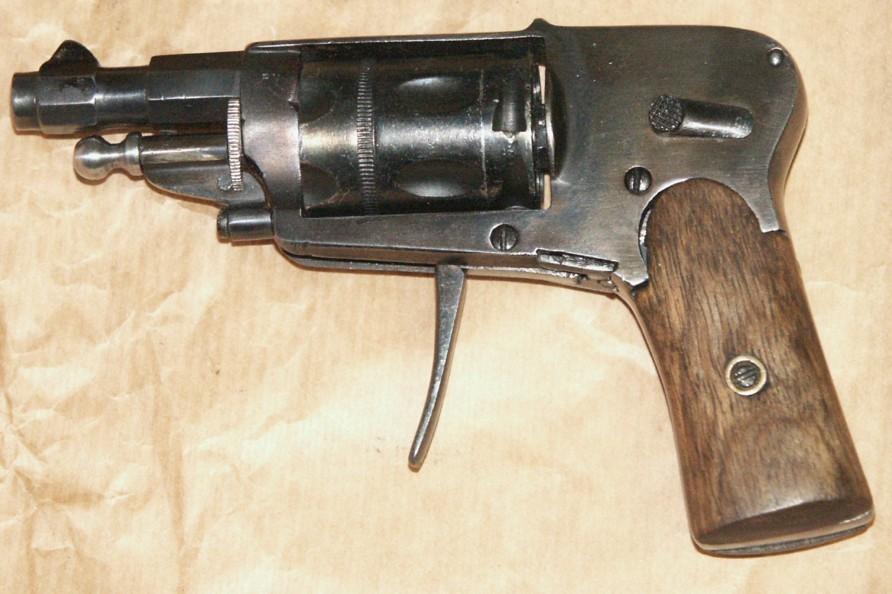
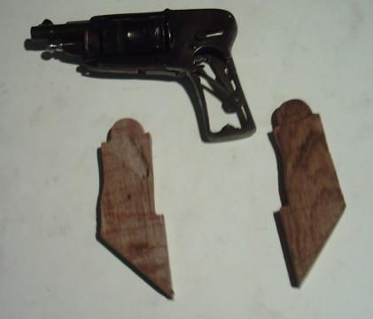
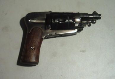
- Pistol-type revolver, concealed hammer, 6 shot in 5.5. Velodog calibre, central fire, folding trigger.
- Grip plates in an unidentified plastic material
- No maker's mark nor logo
- No visible proof mark, no control mark
- Letters PV only on left side of the chamber
- HAMMERLESS in block letters on top strap
- All visible parts are stamped with a 4
- Unreadable mark on the rear face of the cylinder, appears to be a 4
- Rifled barrel 4 grooves clockwise
- Estimated date of manufacture: 1900-1905
- Estimated origin: Liège
The Belgian 5.5 mm Velodog calibre leads me to think about a Liège origin. I have a very similar revolver in my collection, but in the French 6 mm Velodog, which was also in use in Spain. Mine is a "LeBrong", made in Eibar by Crucelegui Hermanos. However of the same general pattern, both revolvers show many minor differences. Both have the same alternated octagonal and round sections to the barrel. Mine has also the word "HAMMERLESS" in blockletters on the top strap, same type of lettering but slightly larger.
Close examination and diagnostics
- Lock mechanism stuck due to unknown cause
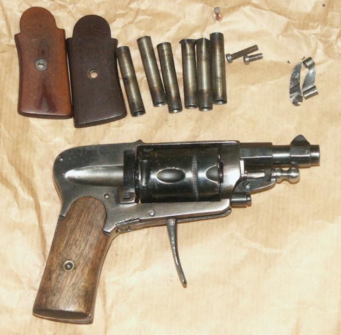
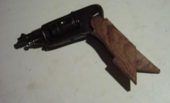
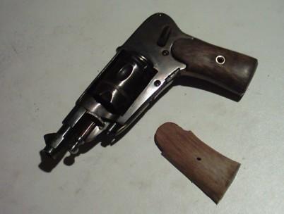
- Grip plates are not original: they are too thin and are maintained by a modern screw and an hexagonal bolt mould in the plastic
- That screw also enters from the right instead of the left
- Cover plate and its screw are missing
- Ejector rod lug is missing and has been replaced by a new one, obtained by bending a piece of thin iron foild into shape; it is also too short
- The ejector rod itself may be a replacement as well. Its copper or brass head looks weird.
- Original color has totally been removed
- No traces of rust nor pittings, but the gun has obviously been cleaned and polished
- Rest of the gun is in good general condition.
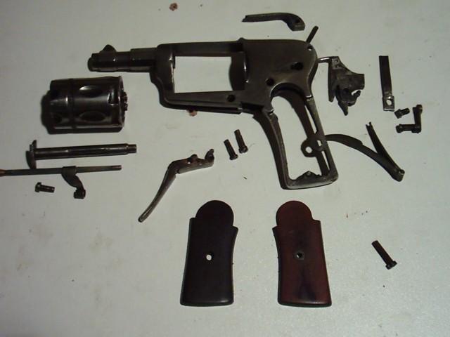
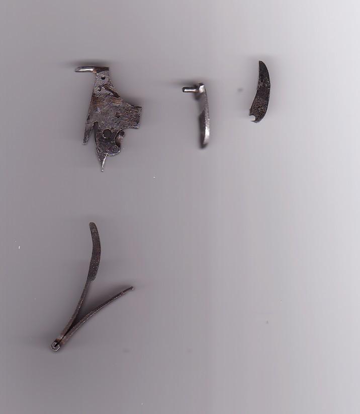
Appearing when disassembled:
- Firing pin bended, which blocks the hammer and is probably the cause of non-working of the lock mechanism
- Pawl axis broken
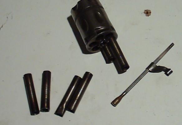
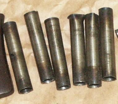
- Thin copper tubes have been forced into the chambers, which prevents the gun to be loaded. (Amateur neutralisation).
The grip plates appear to have been made from modern ones in ebonite or hard plastic, wood imitation, and probably coming from a modern automatic or even alarm pistol. That material can be easilyfiled and polished. The revolver has also been cleaned and deep repolished, and the job was done regardless of all stamps and marks.
The thin copper tubes have been forced into the chambers with a hammer, that has left traces on the rear face of the cylinder. Original catridges cannot be introduced into the chambers.
Repairs to be done
- Removal of the tubes out the chambers
- Reshaping of the firing pin
- Replacement of the pawl by a new one, copied on the original
- Replacement of the cover plate and its screw by new made parts
- Try to find a similar or adaptable ejector rod lug, or make a new one on basis of a known and acceptable model
- Make new grip plates on the normal pattern, a screw and two copper washers.
EXTRACTING THE TUBES OUT OF THE CHAMBERS
That kind of amateur neutralisation is always delicate to reverse, for one walks blind on an unknown path.
I state that the tubes, that are very discrete, are in fact quite thin copper tubes, forced from the rear into the chambers and a few mm shorter than the chambers themselves.
I first thought they were empty shells of which the rear part would have been cut off, but very visible traces of a hammer on the rear of the cylinder eliminates that idea, for no hammer would have been needed to introduce them. Anyway, i make a first trial by pushing carefully with a punch on the forward end of one of the tubes and tapping gently. I got lucky on the third one: my punch engages the edge of a tube and I can push it out through the rear with gentle tappings. It appears to be a section of a very thin, copper-like tube, that shows traces of heating on its forward end.
Luckily, the tubes are not brazed nor glued, but simply forced into the chambers.
I try to do the same in the other chambers, but in vain. The point of my punch has a too small surface; it rips and does not engage the tubes edges. I thought then about making another punch of the exact diameter of the chambers, that could lend on the whole circumference of the tubes. That idea, however, lead me to think about trying to push the tubes out using the one i had already extracted as a punch.
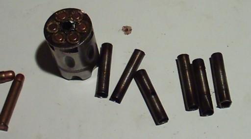
This time, it works. I can push all the tubes out at the rear of the cylinder, by introducing the first tube from the front and tapping gently. Once they are out far enough, i can extract them with pincers.
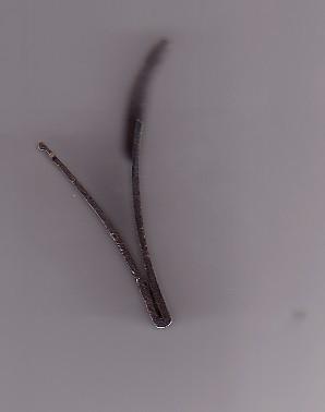
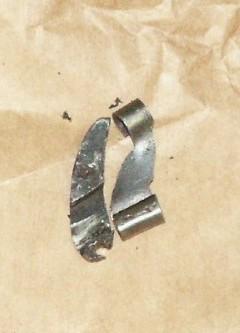
After 5 minutes, my cylinder is free and it looks intact. The photographs show the extracted tubes and the cylinder, loaded with six 5.5 mm calibre Belgian Velodog cartridges.
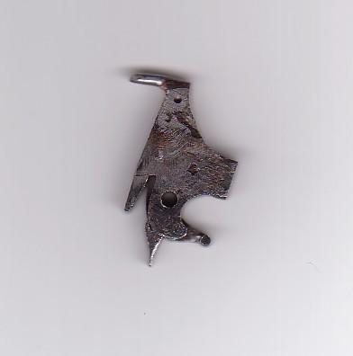
CORRECTING THE FIRING PIN
A close examination of the concealed hammer shows once again that someone else has been working on the revolver before me. The original firing pin, which is normally integral with the hammer block, has probably been broken. To replace it, the guy before me has cut a longitudinal slot into the head, wherein he placed a flat piece of metal, with on the upper part a thicker area, which he has given the shape of a new firing pin. then he has punched a small pin through the side and made a copper brazing to hold it all in place. It is well done and very strong.
Curiously however, the firing pin is bent and strucks well into the percussion channel, which is probably the main cause for the lock mechanism to block.
I bend the pin straight again with pincers, very carefully, and correct its underside with a file.
In a case like this, one must be very careful in order not to break anything. The parts cannot be heaten, as the heat could cause the brazing to melt loose.
The operation is done in three times, bending and filing a bit then assembling the hammer into the frame, until it enters its channel ad fundum and comes out again freely, by a simple inclination of the revolver.
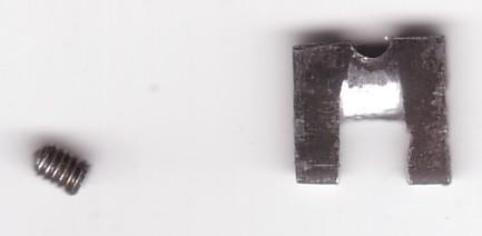
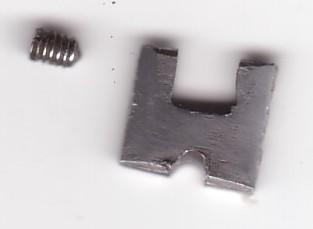
MAKING A NEW PAWL
When I disassembled the gun, I stated that the pawl was broken at the small perpendicular axis that connects it to the trigger block. I assume rust or dirt has glued the axis in its hole, and that it broke at the pawl side when someone squeezed the trigger. Usually, those axes are forced into a hole at the bottom of the pawl, and forged together. The hole is torn open.
It is impossible to braze those tiny parts together, because they are too small and the brazing would never stand the pressure of the spring. I have to make a new pawl, which is quite delicate to do, and I'm glad the original one has not been lost, because I'll need it as a model.
Note
***Arms of the Velodog or Puppy Hammerless type made at the end of the 19th century, have only one spring, that activates the hammer, the trigger return and the hammer rebound.
These springs are complex and difficult to make. Their measurements must be exact, because they work on three points while they are supported by only one. The upper arm activates the hammer, while the bottom one makes two distinctive operations: its vertical projection engages a notch in the thickness of the pawl and pushes it back home when the trigger is released, while the fore edge of the flat portion comes to lay on an oblique flat at the bottom of the hammer, forcing the latter a few millimetre to the rear (rebound).
The only resting point of the spring is a small pin at its right side that engages a hole in a raisen portion of the internal face of the frame. So there is only a support at one side, which also means that the notch in the pawl must be of the right angle, in order to avoid any false pressure, which would cause the spring to break. Those bloody springs break easily.***
I'll make my new pawl out of a piece of an old broken spring, which has just the right thickness. Of course, I soften it first.
First I drill a hole of 1.5 mm diameter, more on the right side of what will become the internal face of the pawl (the face against the trigger block). By holding my copy and the original side by side squeezed in a horizontal vice, i can start the spring notch and give it practically the same angle.
I use a square file of about 5 mm thick. The ridge at the bottom part of the notch, must be flat, in order to avoid the spring projection to slip away and stuck between the pawl and the trigger block. It is a matter of straight filing.
In the meantime I have cleaned the original pawl axis that will be re-used.
Once deep enough, I give the notch the right angle, which is 45° in the front half and about 55 ° in the rear half, in order to allow the pawl to come out, turn the cylinder and retract again under the spring pressure.
Then I give my pawl the right curve, on basis of the original one. I make it too long at purpose, so that I can correct it. The original one may be worn and too short, so that the cylinder would not align correctly, and that is something I can't check since the pawl is broken. A right alignment of the chambers and the locking notches depends on the proper length of the pawl.
Now I force the axis into the hole on my new pawl, making sure it is exactly perpendicular. I heat both parts well red and tap them gently in order to forge them together.
It looks OK.
Now I heat again at cherry red, I temper hard and i make a return in oil, like I would do for a spring. This operation is to make the notch wall stronger, because that is a weak point on the pawl.
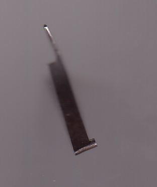
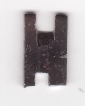
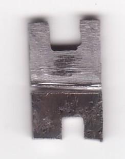
MAKING A NEW COVER PLATE
As I did for the pawl, I decide to make the new cover plate out of a piece of an old broken spring. Spring steel is not especially better for that kind of work; but when it has been softened, it is very easy to work on. Besides, it's a way to recycle the scraps I always keep.
Looking at the place the plate takes into the frame; one can see that it has a slot in which the rear of the trigger block engages, and that its rear portion is asymmetric. Traditionally, these small plates have dovetail-cutted edges and slide into the frame the same way as the screws which mean they enter from the left. The plate is hold in place by a small screw, either on one of the sides, or, like in this case, in a hole that is half on the plate and half on the frame.
I cut my plate and shape it to the right dimensions with a file, caring for its little concave profile and its dovetail edges. That work is quite easy to do. At the internal side,
starting from the rear of the slot, I file the edge in a 45° oblique, in order to let the trigger block move freely. The opening in the plate must be as tight as possible to the trigger block, without however block it.
The same goes for the pawl: since I left a larger area as on the original one around the axis, in order to increase its resistance, there is a risk to see it stopped too early in its way down by the cover plate, which would also hinder the mechanism. In order to help that, I had already filed the cover plate thinner at the inside, so that the pawl would have enough room to return in the resting position.
However, when I assemble the gun to check that, I state that the pawl is still coming to soon against the cover plate, which prevents the hammer to rebound and the trigger nose to take its position below the sear.
The problem comes from the fact that the gunmaker who made this revolver, has positioned the hole to the pawl axis, too low on the trigger block. To correct that, he would have had to shorten the pawl or to make a new trigger block, which is not easy; or to fill in the hole and drill a new one a bit higher, which is not the easiest either. So he chose the easiest way by filing as much as possible the area around the pawl axis, which caused that part to become weak and to break. The broken pawl is the very original one, as it has a number 4 stamped on it like all other parts of the revolver.
In order to avoid making the same error, I cut an aperture in my cover plate, in order to allow the bottom of the pawl to come down a little more. I have seen that kind of tricks on other arms that looked to have been repaired years ago.
Once my cover plate finished and put in place, I mark the place for the half screwhole; then I disassemble the plate again and I cut a round notch with a round file. Then I assemble the plate again, and i finish the hole by making it well circular with a 3.5 mm drill. Then I screw in a headless small screw that I had from scrap.
As I already said before, there are no rules at all for the shape or the size of those screws.
Now I can polish the plate, taking care not to damage the frame.
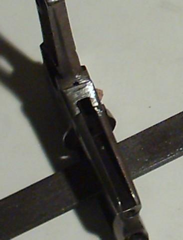
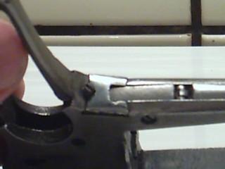
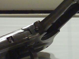
Making a cover plate is not a difficult job, as long as one works carefully. The photographs show the cover plate being made, its position on the frame, and the screw.
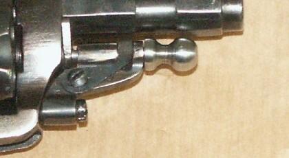
EJECTOR ROD LUG
Ain't I lucky? In my "war treasure", which consists in various cookies boxes full of screws, scraps, broken parts and God knows what else (I'm not sure I do), I find 3 Bulldog-type lugs, of which one can perfectly be fitted on my little patient, provided I make the holes for the screw and the rod a bit larger. That takes me only a minute, with a small drill.
The lug has no spring, but it still has the spring screw.
So I cut a small flat spring out of an old clock spring, with a projection at the upper part, to engage the aperture in the rod channel. I lend it a bit, so that it can hold the rod and prevent it to slide out.
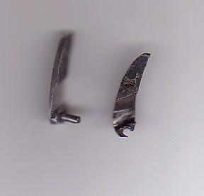
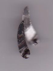
As the ejector rod head has been lost and replaced by a curious cone made with some copper brazing, I make a new one in a portion of a carpenter's nail, that I squeeze into the mandrel of my electrical drilling machine and file to shape according the current model of the time. Now I just have to drill a small hole in the rear face of the head, and braze it on the rod, using the rest of the copper brazing I just removed: once the head in place on the rod, I heat both until the copper brazes them together again.
Old part.
New part.
REBLUEING
However the revolver has been completely repolished, the portion of frame that is normally concealed behind the safety catch still shows traces of case-hardening colorations. So the gun was originally case-hardened, with a dark blue barrel and cylinder.
As case-hardening cannot be done by amateurs, because of the highly toxic chemicals it requires, I decide to try to blue the entire gun, the way I usually do: heating 3 times and alternate with oil cooling.
Although the barrel and cylinder regain their dark blue original colour, I am surprised to state that the frame refuses to get over the yellow coloration. Yet the temperature in my furnace is like usual; so I decide to make more than 3 heating. After the 4th one, I can see that the blue -green stains of the original case-hardening colorations tend to come back. I never saw that before.
After 6 heating of 15 minutes each, alternated with oil cooling, about 80 % of the original case-hardening colorations have come back, and the colours do not change anymore. The stains are faded, but they are back. This is a big surprise; I would never have thought I could recuperate these colours on a piece that has been white polished.
I can't even explain it; I think that the chemicals that are used for case-hardening, affect the deeper metal surface.
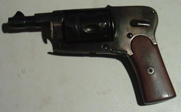
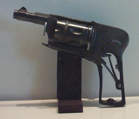
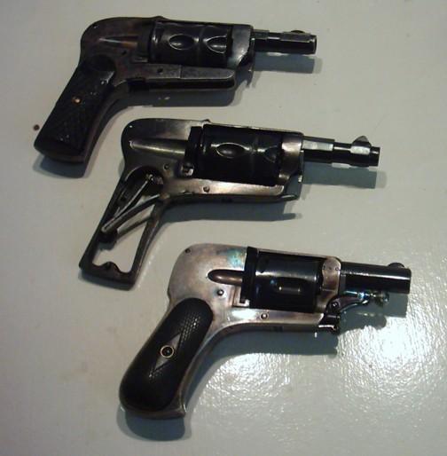
Presented between two guns of the same type, the one used and the other one in mint condition, I think my little patient looks quite good!
REASSEMBLING THE GUN FOR CHECK
At this stage, I reassemble the original grip plates and I check the general working. It looks good, except for the pawl that sometimes stuck into the ratchet teeth.
I disassemble the whole thing again, and make the pawl head a bit thinner - it takes several trials - until the lock mechanism works normally. The only problem is that the cylinder does not align perfectly the barrel. This is not caused by the length of my pawl, which is actually a bit loger than the original one. The iconoclast, who has forced the copper tubes into the cylinder, has been using a hammer to do that, and he has damaged the ratchet teeth and the whole rear face of the cylinder. I was able to file the rear face flat again, but there is nothing I can do to damaged ratchet teeth. That problem will never be solved.
Despite that, however, I think our little patient has recovered a great part of its health...
MAKING NEW GRIP PLATES
Houston, we have a problem....
Usually, when I make new grips for a gun, I first cut them roughly to shape, and then I adjust the best I can to the metal parts in the upper zone. Then I drill the hole for the screw, and I assemble the rough grips to the frame. Then I finish them on the frame, so that I can make them fit exactly. I usually get an acceptable result working that way, because I can correct possible errors all the way through.
Of course that working procedure causes my tools to make digs and scratches on the grip frame, but that is not a problem, as I make the grips plates prior to finish the gun.
In this case however, I have put myself in a difficult situation since I already reblued the gun. At first I intended to make a trial, but the amazing results have leaded me to finish the reblueing, and now I dare not take the risk to repolish and have to reblue again, because I don't know how the gun would react this time.
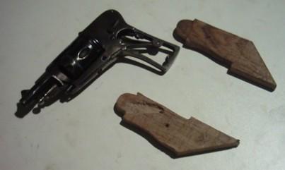
So I am forced now to cut my grip plates on basis of the ones that were originally on the gun, without possibility of adjust them directly on the frame. This is a new experiment for me, and we will see that I still have a lot to learn, because I made errors I could have avoided if I had done what I was used to do.
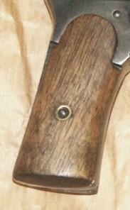
The owner of the revolver has given me some beautiful pieces of rough walnut, so I can choose a nice piece with many veins and the exact place where I will cut the grip plates.
Note
*** In the event I wouldn't have had any walnut on hand, I would have used a piece of beech, which is also a hard wood. And I would have cut it out of an axe grip, which I would have coloured in black to make it look like ebony. Beechwood is good specie for grips; it has often been used in the 19th and 20th centuries for army rifles and muskets stocks. However cheaper and not as nice than walnut, it is hard and very strong.
In this case however, I have the great luck of having nice walnut blocks and lumbers on hand. Yippee.***
Considering the fact that the grip plates should have a thickness of about 1.5 cm at the bottom, decreasing towards the upper part, I first cut two blocks of a thickness a little superior to that. I leave them too long just to make them easier to manipulate.
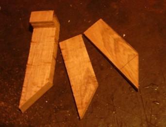
After having sanded what will become the internal side of my future grip plates, I first draw the model on the wood, using of course the original ones as a pattern for that purpose.
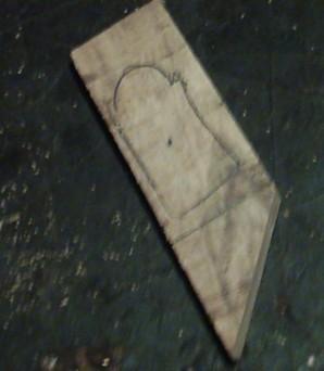
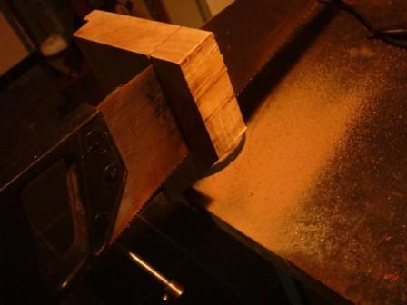
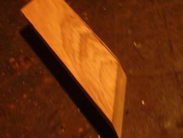
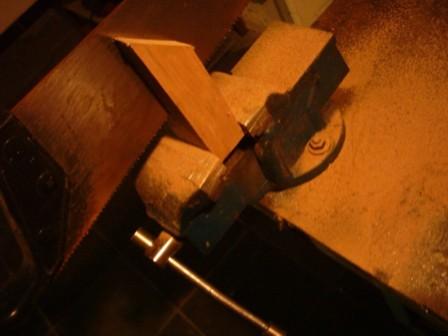
Then I squeeze my block into my vice and I cut the shape roughly with a saw, starting from the upper part that has a round form and two shoulders. In order to get the best possible mounting, i use an old stockmaker's trick: I cut the sides in oblique towards the internal side, which will allow me to correct possible mounting errors.
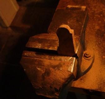
During the work, I frequently put my grip in place on the gun for adjustments. I focused on the upper part, leaving the rest for later.
I work the same way for the other grip plate, in this case the right one.
Spring resting
The right grip gives a new difficulty at its internal side. As a matter of fact, the sole spring on this type of revolvers is always a little larger than the thickness of the grip frame, which causes it to come over the limit around its resting point. That means that a slot must be cut into the internal side of the right grip, triangular and quite deep, which will not only allow enough room for the spring to work, but will also provide it a second resting point.
After having carefully drawned the limits of the slot with a pencil, I dig my slot using a small chisel, first roughly, and I file it smooth afterwards with a small square file.
The slot is deep at the angle, goes decreasing towards the edge, and disappears totally right before that edge.
Then I file the external rounded profile of the grips with a gross file, making sure I make them both symmetric and decreasing in thickness from bottom to top.
After that I choose carefully the exact place for the screw hole, which iI drill with a small diameter drill.
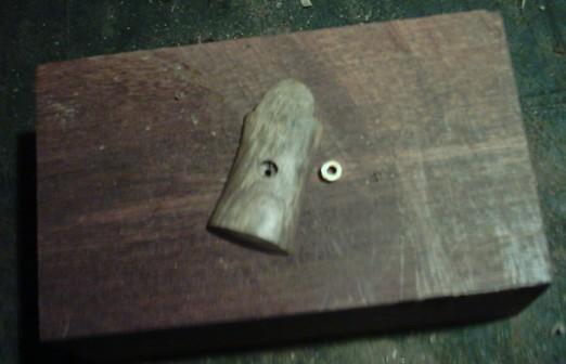
Fitting the washers (escutcheons)
I have on hand a set of original washers and screw, so that I don't have to make them.
I will first mill the hole using a drill of a bit smaller a diameter as the washers, and about 4 mm deep. My grip laying well flat on a piece of wood, I put the washer in place and I force it home carefully, tapping gently with a small hammer that must be done with great care, in order to avoid splitting the wood.
It is often necessary to adjust the hole diameter with a small round file. Actually, the rifled side of the washers should cause it to lock itself into the wood. If the hole diameter is too large, the washer will turn when the screw is being screwed in, which is particularly f....boring.
To avoid the problem, one can put a drip of varnish into the hole to glue the washer in place, or wet the wood and dry it with a hot iron, in order to cause it to stretch out and offer a better holding to the washer.
In my case however, the hole is of the right diameter, and the washers are held tight without any artifice.
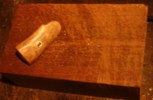
Once the washers in place, I make a first polishing, using a fine file and sand paper, and filing the edges of my washers that must be at the same level as the wood. They must be visible, but imperceptible with the fingers.
FINISH
The only thing that rests me to do now is to colour the grips and polish them. I could use nut tincture for the job, but I like quite much the colour given by the linseed oil.
So I first assemble the grips, then I start polishing them with fine sand paper. Before the last polishing, I take them off again and put them in hot water for a few minutes, in order to force the wood fibbers to rise up. Then I let them dry and polish them again.
After that I oil them with a soft cotton cloth drenched in linseed oil, and I rub them until the wood has taken all the oil.
I repeat this operation 4 times, waiting a day between each time. Finally, I spend an hour or two watching TV while rubbing the grips with my bare hands.
That's it, the gun is finished. It had a long trip back home.
I am not satisfied about the grip plates, the mounting of which is not good enough. I am only an amateur, but I know I can do better. So I already told the owner that I will make new ones some day in a near future, in order to recover my sleep again.
Marcel