CARBINE-TOY RENE WARNANT
Someone asked me to refresh - or restore - an old toy carbine, made by René Warnant of Liège, probably during WWI or in the early interbellum. I can't precisely tell wether the maker was René Warnant, registered at the Proofhouse from 1912 to 1956, or René-Guillaume Warnant-Counasse, member of the same family. Both seem to have been active until after WWII.
Since they could only work under control and on behalf of the German occupant, a large number of armsmakers became workless and forced to look for other sources of income dring those difficult years.
So some found a new activity in the make of toys, which was probably approved by the Germans. This activity has probably been carried on during the interbellum for economic reasons, since the demand for arms always drastically decrease after any war.
The carbine we are talking about is one of those toys. To be honest, I would estimate it was made somewhere between 1914 and 1930.
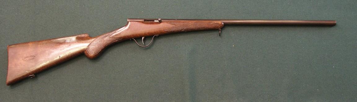
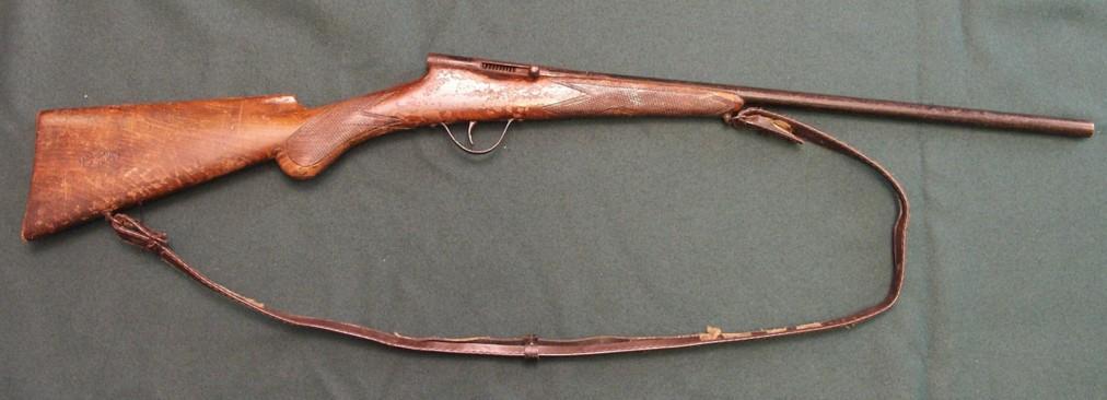
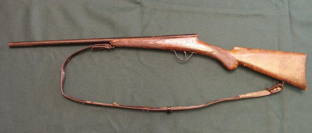
DESCRIPTION (fig 1 to 6)
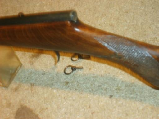
The "weapon" is a small size single-shot carbine, evidently destined to 8 to 10 year old soldiers.
Total length is 78 cm, barrel length 51 cm between the muzzle and the very back stop; shoulder stock is 20 cm between the buttplate and the pistol grip, the latter being 10 cm long. The total weight is less than a lb.
Measured at the muzzle, the "caliber" is 9.5 mm. The barrel is made out of a single steel (?) pipe of about 1.5 mm thick, that houses the entire lock mechanism in its very back part.
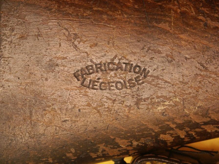
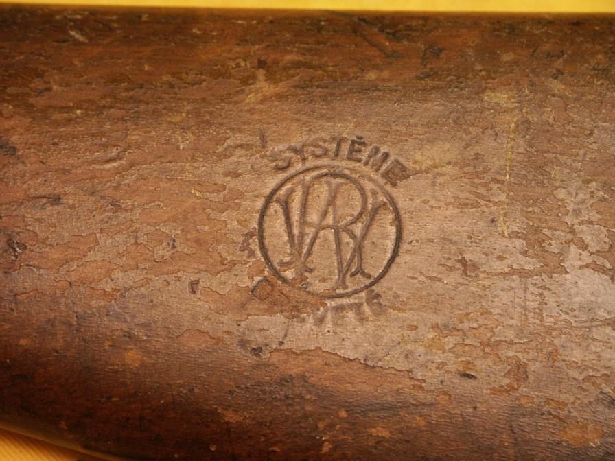
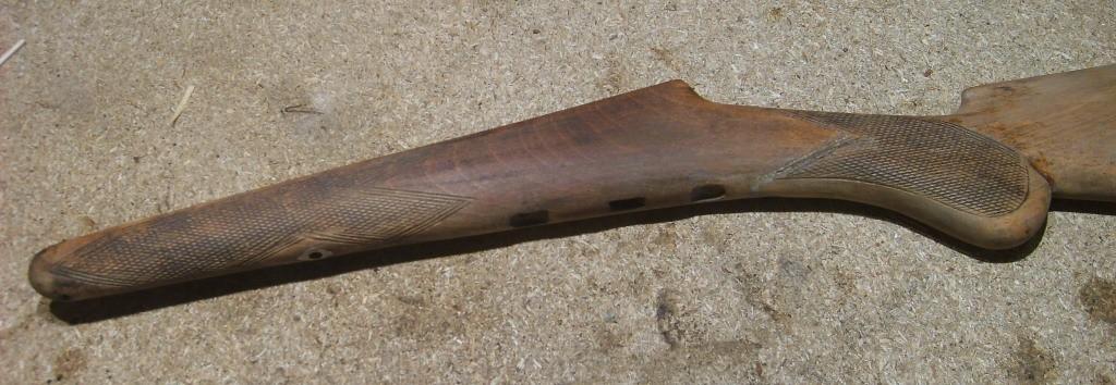
The lock mechanism is a bolt action, the bolt being activated by a spiral spring. The trigger guard is a simple curved flat piece of steel secured to the stock by two single woodscrews. Two round lanyard rings are screwed into the stock, which is made of cheap hard wood, probably beech. The shoulder stock is marked on the right side "Fabrication Liégeoise" (Liège make) in 2 lines in an ellips; on the left side is a round cartouche with the initials RW in the middle and the words "Système Breveté" (patented system) in two words above and underneath the cartouche. These marks are roller-die stamped and are quite deep. Fortunately, they have quite good survived the heavy treatments of many children throughout the years.
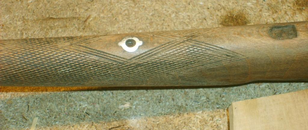
The barrel is attached to the stock by one single screw placed in the middle of the forewood.
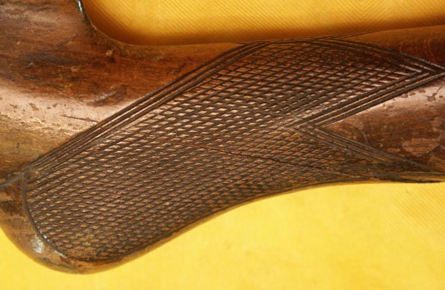
Some details show evidently the piece was made by a professional armsmaker, such as the escutcheon to the retainig screw in the stock, which is of the same type of those found on rifles made in the 19th and early 20th centuries: an escutcheon with wings, perfectly inserted in the wood. Besides, the pistol grip and forewood are nicely hand checkered like on the real ones !
The "ammunition" is the well-known Maynard paper disk (see note below). There is a perpendicular cut in the barrel ahead of the bolt; just ahead of that cut there is a shield in the barrel against which the paper disks come to rest, and in the above part is a cut that is probably meant as escape for the gasses.
The "shooter" pulls the bolt to full cock, puts a Maynard disk verticalli into the transverse cut, and shoots. There are no sights and no safety systems of any kind, since these features are unnecessary on that perfectly safe toy.
The toy is sturdy and evidently made for heavy duty. Thuis one shows many traces of heavy use; the lock mechanism is dirty and full of old oil and God knows what else, but it works perfectly. The varnish on the wood is almost gone, and the wood shows innumerable digs and dents and stains.
The lanyard is irrecuperable, which is not a problem since it is a totally anachronic piece of leather imitation or plastic.
NOTE ABOUT THE MAYNARD PRIMERS
Young guys of my generation (I'm 63) all remember those small rose coloured paper rolls that we used in our toy guns and remained in use until quite late in the 1960's. About 100 drips of fulminate were glued on these rolls, at a distance of about 1/2 inch from each other. However, some of our weapons used small paper disks instead of rolls; those disks were about the size of a confetti, with a drip of fulminate in the middle, and were available per 100 units in small round wax cardboard boxes.
However, few people know about the history of that very old primer system. It was invented by a renown American dentist, Edward Maynard, who was interested in technics and more specially in the problem of slow realoading of the weapons of his time. So he started looking for improvements, more specially on the priming system, in order to enable soldiers to avoid the difficulty of placing percussion caps on a nipple by cold weather with cold fingers or wearing gloves, and so improve the performances of their weapons.
He developed his priming system and had it patented on Sept 22, 1845, under n° 4028.
On the weapons designed for the use of rolls, the primer is placed into a small box located at the rear of the lockplate. Inside that box is a small gear that is actuated by the action of cocking the hammer. The gear pushes the primer ahead until a drip of fulminate comes exactly above the nipple. When falling down, the back of the hammer head, which is sharpened like a knife, cuts away the used pece of the roll.
Right from the start, rolls of 100 primers were produced together with individual disks. Those were placed in pile in a small cylinder (see Butterfield revolver).
The army adopted the system for the Springfield 1851 rifle and paid Maynard the huge amount of $ 75,000.
Although the system was technically very good, it prooved to be desastrous by rainy weather, because the humidity and the rain caused the priming disks and rolls to clog and destroyed the paper bands and disks.
So the system was abandoned, but not completely forgotten, since it found a new way on the field of toy weapons where it remained in use for more than a century.
In the mid-1960's, it would be gradually replaced by another ancestor: the percussion cap (often in plastic !). Today, the Maynard-type primers have become a rarity.
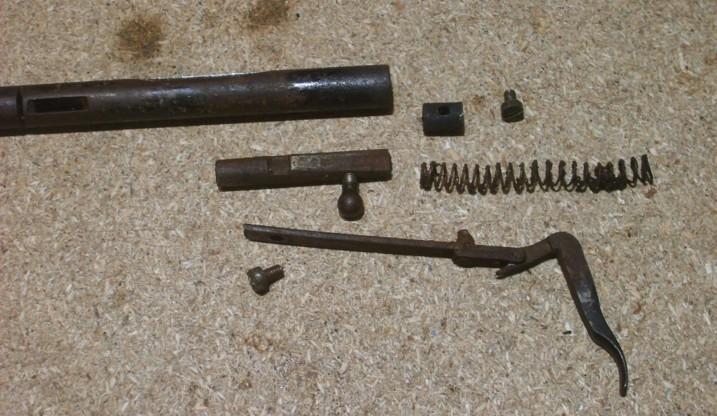
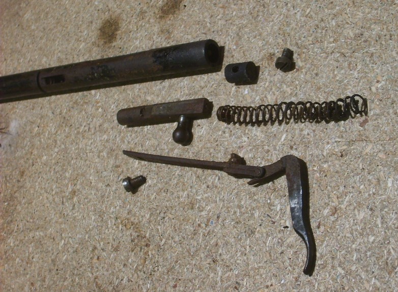
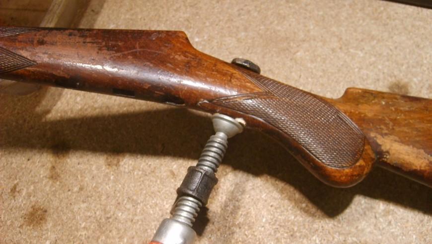
DISASSEMBLY OF THE LOCK MECHANISM (Fig 7 to 9)
Fortunately, disassembling that old piece goes quite smooth.
The barrel lays in a groove cut into the upper part of the wood and is hold in place by one single screw located in the middle of the forewood. This screw, which as told above looks professional with its winged escutcheon, comes loose without any problem. The entire lock mechanism, trigger and spring included, is located in and underneath the barrel.
In the interior part of the forewood, a large nr 13 is stamped. I guess that the exact meaning of that figure will remain unclear; however, the "matching numbers"- freaks among us will be happy to hear that the same nr 13 is also stamped on the under part of the bolt. So our toy bears at least two matching numbers...
At about 11,5 cm from the very rear of the barrel, is a transversal cut of about 1.5 mm, in which the primer disks have to be placed vertically, with the fulminate drip towards the bolt. Inside the barrel, the disk rests against a shield.
About 1 cm behind the transversal cut is another opening, placed on top of the barrel and of which I guess it is an extra exhaust for the gasses. Quite useless if you ask me, but who am I ?
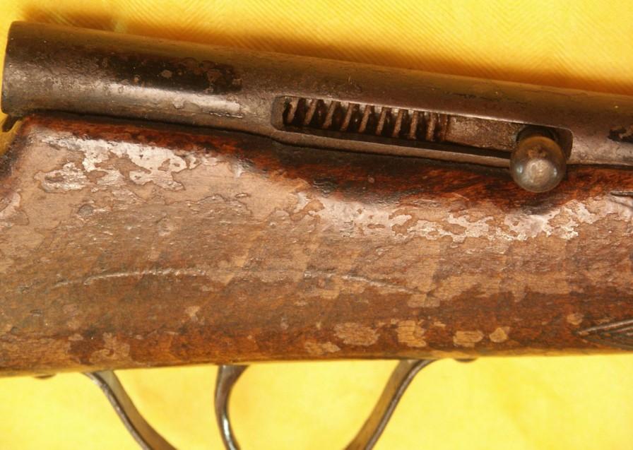
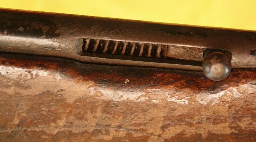
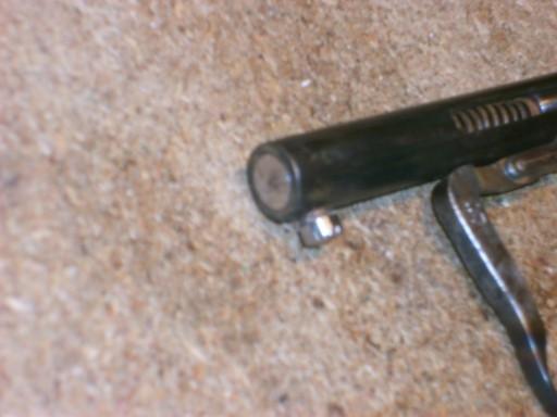
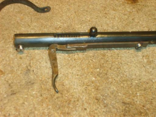
The right side of the barrel shows a larges and longer cut, where the bolt lever head comes out. At the rear end, the barrel is obturated by a metallic cylindrical stop held in place by a sturdy screw.
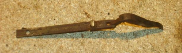
Underneath the barrel is a big flat spring, attached at is fore end by a screw, with a thick vertical cam in its rear part, that enters the barrel through a hole and actually acts as a sear.
The rear of the flat spring is connected to the trigger, which is a simple piece of steel bent at right angle.
The bolt is a solid steel cylinder with on its underpart a notch and an oblic cut probably meant to give a smoother movement. The bolt is actuated by a spiral spring laying behind it into the barrel.
With all due respect, at this point I stated a little flaw in the concept: since the barrel is hold in place by one single screw in its middle and lacks quite of its strength due to the transversal loading cut, it tends to bent under the pressure of the trigger right angle.
The action is simple and ingenious: when the bolt is pulled backwards, the cam engages the notch to hold the bolt in the "full cock" position. Then a primer disk is put in place, and the trigger squeezed. When the trigger is squeezed, the elbow at the right angle comes to rest against the barrel and forces the flat spring downwards, so that the cam disengages the notch and frees the bolt. The spiral spring pushes the bolt forwards so that it can strike the disk.
The whole lock mechanism and its large flat spring located underneath the barrel, inevitably reminds of the "Warnant system" in use in thousands of gallery carbines and pistols...
The mechanism is easy to disassemble, except of course the rear stop, that has probably never been disassembled and is glued by rust and hard oil.
Heating it (not too hot) with a torch and then cooling it brutally into cold water prior to push it out with a thin steel pin make it quite easily loose.
I can now take out the bolt and its spiral spring.
All inner parts are dirty and lightly rusted, but still in good shape, except for the spiral spring that has lost a little of its strength and needs probably to be replaced. So I will start by putting all those loose dirty parts for a few days into a jar of petrol; in the meantime I can work on the stock.
THE STOCK
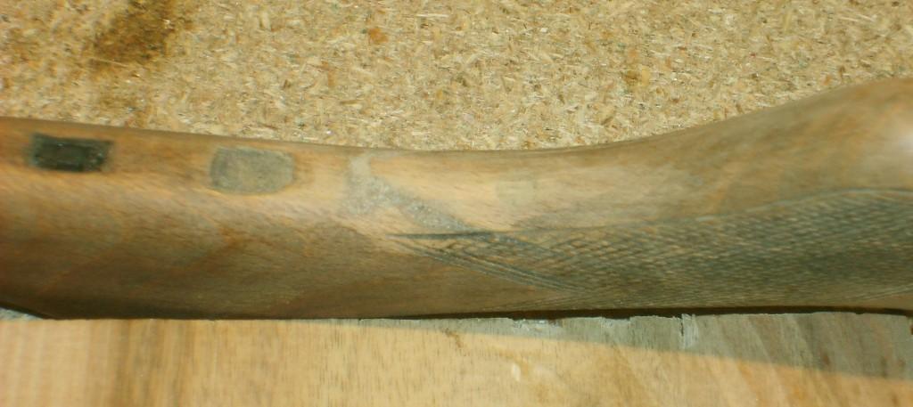
Holy cow...the condition of the stock shows a very heavy use! The wood is full of digs and dents, scratches, stains, and the varnish is damaged all over.
There is but one solution: I'll have to remove completely the old varnish, repolish the wood and varnish it again.
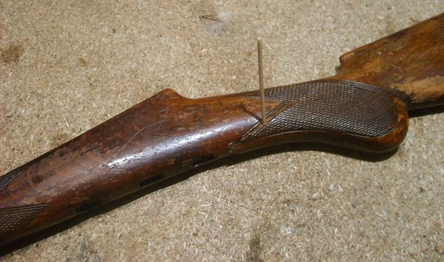
The stock has been partially broken between the trigger guard to about 3/4 of the pistol grip. Although the crack is partially hidden by the checkering,
I decide to repair it.
First I open it carefully, and hold it open with a tooth picker, so that I can inject glue between both parts, using the point of a knife. (fig 10)
Then I remove the tooth picker and drill a vertical hole of 6 mm diameter and about 3 cm deep straight through the crack; in that hole I drive an englued hard wooden plug (Fig 11).
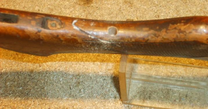
Then I hold it all in a hand vice, not too tight in order to avoid damaging the wood (Fig 12 and 13).
Once the repair has dried, i put a thick layer of paint remover on it. For that purpose I use a simple commercial paint remover in jelly form. That product is very efficient against old varnish and paint but has no effect at all on metal, wood and glue. Just put a thick layer of jelly over the old varnish and let it do its job. After a while, all residues of varnish can be removed with a dry brush.
Of course, te wood needs then to be carefully polished.
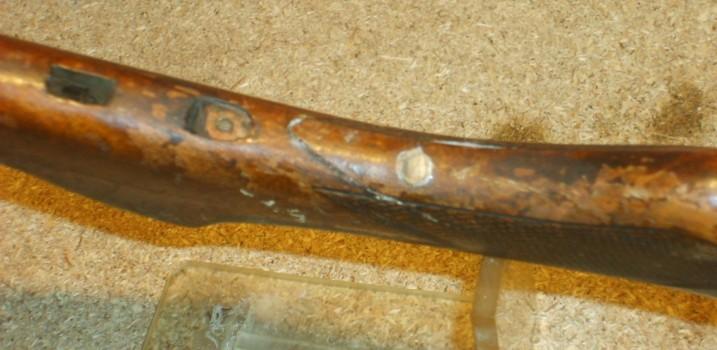
Fig 14 to 17 show the stock cleaned and polished; my plug is now practically invisible and cannot be felt with the finger. I just need a finishing touch in order to eliminate most traces of the crack.

My first idea was to take off the escutcheon of the barrel retaining screw in order to flameblue it, but I renounce because of the risk of damaging the wood.
I'll have to cold blue that part.
I intend to recolor the wood - not too dark - and then apply two layers of varnish. The great advantage of this kind of varnish, that has to be applied with a cloth instead of a brush, is that its surface dries immediately, which allows easy manipulations and prevents dust to englue on the surface. However, a delay of at least two or three days must be observed before applying the next layer because the varnish hardens very slowly.
Pictures 18 to 20 show the recolored stock with the first layer of varnish. I first recolored the stock using a small wet sponge in order to avoid colour differences in that wood that absorbs moisture very rapidly. I waited 2 days before applying the first lay of varnish. The results are encouraging and the drying time is finally acceptable.
THE METALLIC PARTS
All parts of the lock mechanism are dirty and lightly rusted, but that is not a problem. A few days in a petroleum bath have loosened the rust, which can now easily be removed using a metallic brush. The cleaning operation reveals a number 13 on the trigger, as it appears on the bolt and the stock.
The barrel was originally simply painted black. So I bought a glossy black paint, but the owner let me know he would prefer a blueing "as on the real ones".
That is quite different of the original, but it's his personal choice, so I'll try to blue the barrel. I'm not sure I will succeed, since the quality of the metal is not the same as on "the real ones"...
I removed the remains of the original black paint using sandpaper, and then polished the parts using finer sandpaper and finally extra-fine steel wool (1000)
All traces of rust and dirt are removed, but I can't get the "mirror" polish on that kind of metal. Cleaning reveals once again the same nr 13 underneath the barrel. So the numbers match on 4 elements of the toy already.
Surprisingly, the barrel not only accepts cold blueing, but gets quite dark from the first lay of liquor. As a matter of fact, only 3 layers will be needed to obtain a nice dark blue. I think the owner will be pleased as well.
The bolt will be left white, but its ball, the trigger, the screw heads and the lanyard rings will be flame blued, which is much nicer.
Pictures 21 to 23 show the cleaned lock parts and the reassembled lock mechanism. I apologise for the quality of my photographs...
ABOUT THE CONCEPT FAULT
The conceptual flaw would be relatively easy to correct so that the trigger elbow could not bent the barrel again. To get to that result, I could replace the short screw that maintains the back stop by a longer one that would go vertically from the rear of the trigger guard through the stock and engage the rear stop.
However, since the toy will not be used again, I don't think that change would be necessary, so I renounce.
The last job is to clean and reblue the trigger guard. I burn the remains of the original black paint with a torch and remove the remains of paint with a metallic brush prior to polish the metal as well as possible with sandpaper and steel wool. That operation reveals...a number 13 on the inside curve of the guard.
The guard can now easily be flame blued and reassembled.
So, my toy is now more presentable, and deserves in my opinion a good place in a collection of Liège arms.
Marcel