10.RESTORING A LIEGE-MADE REVOLVER SIGNED Philippe COUNET
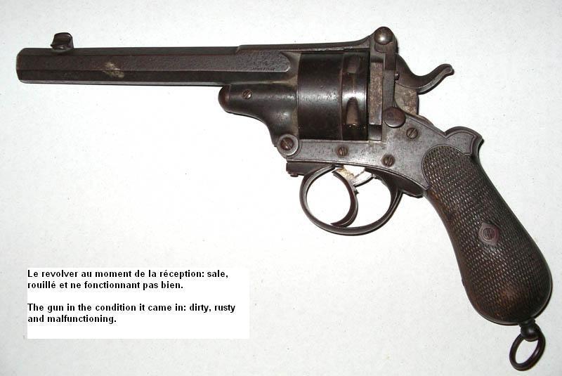
A friend brought me a large caliber Liège-made revolver that is in a quite bad condition.
It is an officer's type topbreak revolver in the .45 or .450 caliber, six rounds cylinder, probably destined to the army, signed Philippe Counet gunmaker at Liège (see more about him on our site - link "Belgian Weapons, Identified Craftsmen"). This weapon was probably manufactured in the early 1870's
Despite its bad condition, one can see at first glance that this is a high quality gun, solid and powerful, very well made and finished.
IDENTIFICATION
- Double and single action topbreak revolver
- Caliber .45 or .450, six shot cylinder, rebound hammer
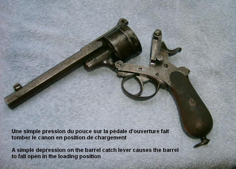
- Opening mechanism: a spring-loaded lever is mounted on the left side of the frame behind the cylinder. This lever is connected to a catch that moves laterally into the upper rear part of the frame, above the hammer, holding the gun closed. A thumb pressure on the bottom part of the lever causes the catch to move laterally out of the frame, liberating the barrel lug and allowing the gun to fall open.
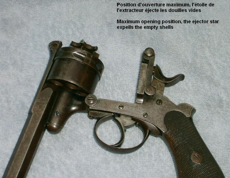
Like on the Webley and Smith&Wesson topbreaks, the barrel lug hinge includes a part called "extractor ratchet", which in his upper part has a pin that pushes the star extractor out to expel the empty shells.
Once the shells have been expelled, the extractor star moves back into the cylinder, allowing for reloading.
- Heptagonal barrel (7 flats) rifled 5 clockwise - wide grooves and nerves
- Bag shaped grip with a large rear busc, allowing for an excellent hand grip
- Chequered walnut grips
- The frame and grip show a nice discrete line engraved along the sides in the style of those found on the Adams and Tranter revolvers. The quality of the original make of our Counet is evidently equal to that of those magnificent English revolvers.
The actual condition of the gun does not allow seeing if any part of the original finish is remaining.
Markings
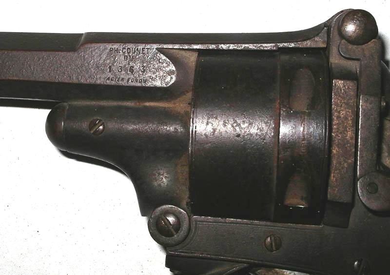
- On the breech, right side in 3 lines: Ph Counet Bté, 133, ACIER FONDU
- On the grip frame, under the left grip: initials MH, smaller initials NM. On the right side, initials JO
- Rear face of the cylinder: 17
- Front face of the cylinder: very small B under crown
- Side of the cylinder: ELG* proofmark in an oval, controller's initial Y under crown. These proofmarks indicate a pre-1877 manufacture.
- Interior side of grips: left a roman fig Vll and initials PC under crown; right the roman fig Vll and Arab figure 3.
No other marks are visible so far. The fact that the name of Ph Counet appears on the gun does not necessarily mean that it was made by him. Identical revolvers have been observed with the signature of Auguste Francotte. However, the original patent was granted to Counet.
CLOSER EXAMINATION AND DIAGNOSTICS
- The weapon shows an overall rust layer and light pitting here and there
- The trigger return spring is missing
- The cylinder won't turn when the trigger is squeezed with the barrel pointing upside, which indicates a broken hand spring.
- The hammer safety does not work. It is not exactly a rebounding hammer, but the hammer can normally be pulled a few mm back and should stay in that position, so that the firing pin is out of the percussion hole and any accidental firing is prevented.
- By opening the gun, the star extractor won't come out; this is due to the "extractor ratchet" which is missing.
For the rest the gun looks complete and in good condition. The rust layer appears to be superficial, and doesn’t seem to have blocked any screw.
(Photo 01a, b et c : reception)
WORK TO BE DONE
- Electrolytic de-rusting and cleaning of all parts
- Replacement of the missing trigger returns spring
- Replacement of the missing or broken hand spring
- Replacement or repair of the small hammer safety level spring ands possibly resharpening of the hook and notches edges
- Replacing the missing extractor ratchet.
DISASSEMBLING
Barrel-cylinder group (pic 02)
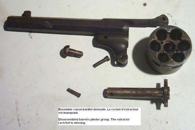
This group is very easily taken apart, since all screws turn freely despite the rust. Once the group disassembled, it becomes evident that the whole extractor ratchet is missing.
Lock mechanism and grip (pic 03)
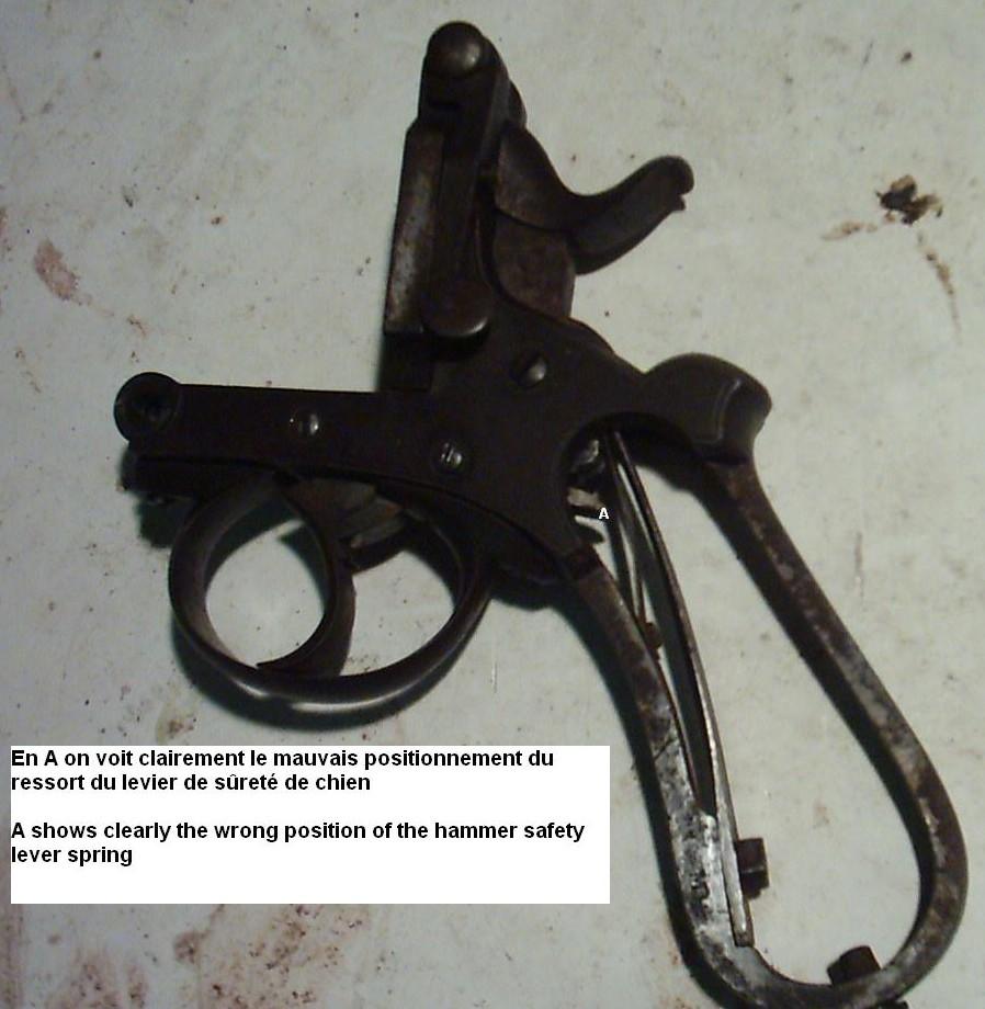
This goes smooth as well. Once the grip plates removed, I can see that the small flat spring that actuates the hammer safety lever lays above the lever while it should push it up from underneath. It is a small flat spring attached to the grip frame by a small screw, in front of the main spring. It is meant to push up the rear part of the hammer safety lever, so that the latter can engage the hammer bottom and keep the hammer backwards when the trigger is gently squeezed or the hammer pulled back a few millimetres.
This spring has evidently been wrongly mounted by one or another patented donkey and creates in this position an obstacle to the main spring; besides, the hammer safety level cannot function normally since it is not pushed up by the spring.
The trigger return spring is missing as well. It seems to be a classical V-spring, a part that can easily break.
Complete disassembling (pic 04)
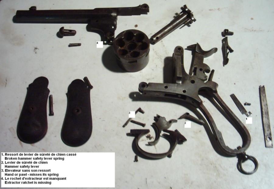
Carrying on the disassembling, I can see that the hand spring has been broken flush with the hand itself, which is the reason why the cylinder only turns when the barrel is pointed downwards. On the pic are marked the different parts that need repair or replacement.
As I was afraid of, I broke the end of the hammer safety lever spring by dismounting it.
The inner parts are perfectly polished and adjusted, and show no wear at all. This is really a high quality weapon.
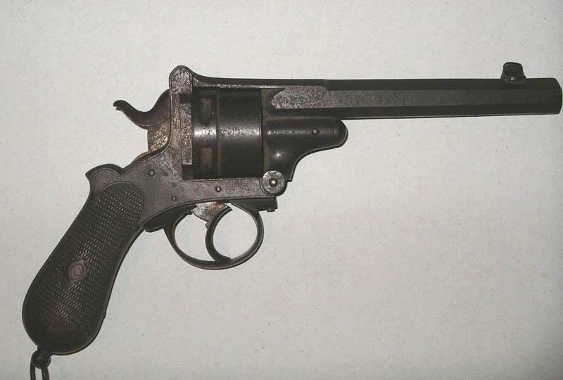
ELECTROLYTIC DE-RUSTING (Pics 04a and 04b)
As usual, I reassemble the entire gun except for the springs, and leaving all screws loose in order to allow the acid to penetrate in every small hole. This operation is not new and has been described in details in a previous article.
However, since the rust layer looks rather thin, I decide to slow down the reaction and to observe it. To keep the reaction slow, I simply add one litre of distilled water to my normal solution, so I have now 6 litres of distilled water for 250 gram of soda.
The idea appears to be excellent, because the slow chemical reaction produces less froth on the surface of the bath and allows me to follow the evolution step by step.
After 3 hours of this treatment, I take the revolver out of the acid solution and wash it with cold water and a sponge.
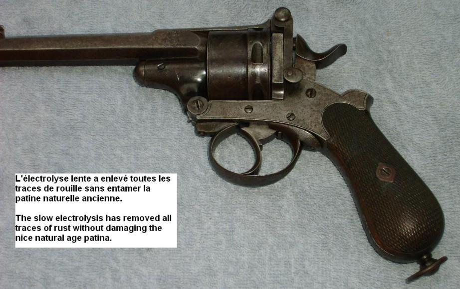
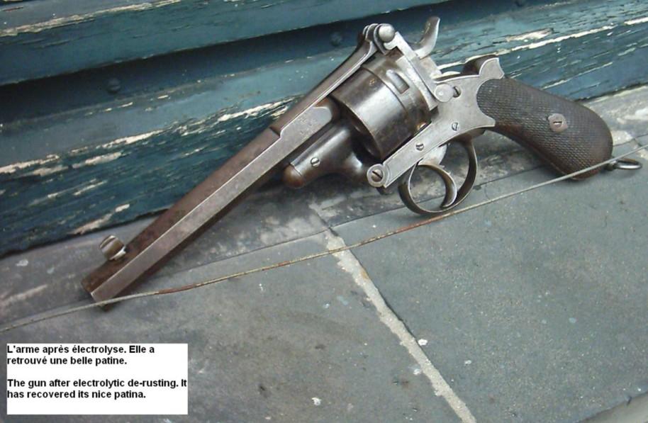
The rust layer is almost completely gone, and the remains are totally soft and very easy to remove with the sponge. I have great pleasure in stating that the probably quite recent rust did not have time enough yet to damage the nice age patina. Here and there the frame still shows good remains of a bright cold blueing that is never seen on modern arms.
I assume that the weapon was in this condition when it was put away in some humid environment, which has caused the rust. Fortunately, the gun was found before the rust had time to cause irreversible damages.
There is only very small pitting here and there. Pics 01, 04a and 04b show clearly the difference before and after the electrolytic treatment.
REPLACING THE TRIGGER RETURN SPRING (picture 05)
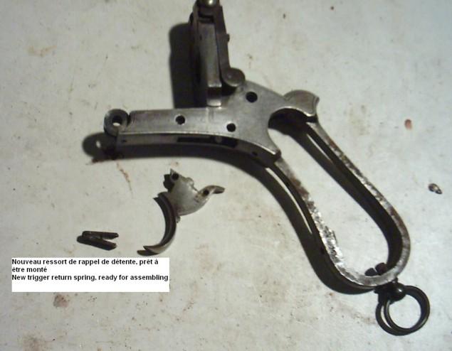
Nothing new here either. I cut a V-shaped spring out of a portion of intemperate spring steel bar, leaving both arms flat and quite thick since my spring must be quite strong. It give it such an angle that, once mounted in place in the frame, its upper arm is horizontal and lies just under the forepart of the trigger block. Then I file the end in oblique and open the angle a little bit more, in order to create a permanent tension on the trigger when it is in resting position.
Then I heat my spring cherry red; when the metal starts sparking, I cool it brutally in a jar of cold water to temper it hard. Then I wipe it dry and polish carefully its surface in order to make the metal become white again (when tempered at the right temperature, the steel surface becomes dark grey).
I finish the job with a "return in oil" to soften the spring again: I heat it gently on my gas furnace, until it gains a deep matt blue colour; then I take it away from the fire and cool it in a bowl of common engine oil.
My spring is perfect, very strong and elastic. All I have to do next is a final adjusting of its dimensions with a Swiss file, and I obtain a trigger pressure that is just strong enough and at the same time very smooth.
REPLACING THE HAND SPRING (pictures 07 and 08)
Replacing a hand spring is usually easy to do, but in this particular case it appears to be more difficult since the bottom part of the hand that has an oblique split to hold the spring is damaged and cannot be used anymore. I'll have to be somewhat inventive. As long as the original one can be re-used, I don't want to make a whole new hand.
I start by filing the bottom of the hand flat again, and then I cut an oblique split into it, that will hold the new spring. The problem here is that most metal saws found in tool stores are too thick, which makes cuts that are far too wide for such a thin spring. Since I can't find the special, very thin saw used by the old gunmakers, I solve the problem by heating the part a little and then squeeze it in my vice, so that the split becomes a very narrow line.
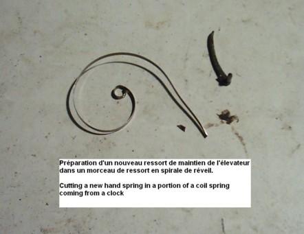
The spring itself is cut on the proper dimensions in a portion of an old clock coil spring. I keep repeating that those clock springs are the best there is for cutting all those tiny pawl and other small springs used in weapons.
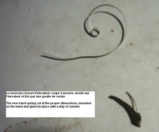
As usual, I push the spring home in the narrow split, I squeeze it a little more in the vice, and I finish by gluing it in place with a small drip of varnish. Once dry and hard, the varnish will hold the spring in place and prevent any unwanted motion during the reassembling. The spring must be perfectly in line with the body of the hand and may not come out of its channel when the gun is in use, otherwise it would jam the hammer.
REASSEMBLING THE TRIGGER MECHANISM (pics 9 & 10)
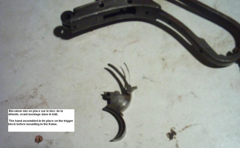
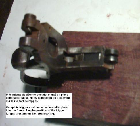
Once the varnish has dried, I set the hand in place on the trigger block and I reassemble the complete trigger into the frame. Picture 10 shows the position of the trigger return spring engaged under the forepart of the trigger block, the trigger in resting position.
I squeeze the trigger firmly a few times in order to check the motion of the hand in its channel and make sure that nothing can jam.
REPAIRING THE HAMMER SAFETY LEVEL SPRING (pics 11 & 12)
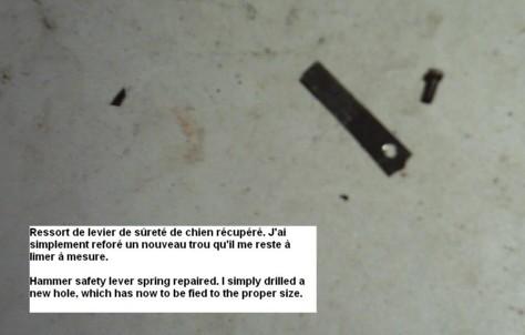
That spring was wrongly assembled in the frame, and I broke it right at the screw hole when I unscrewed the small bolt that holds it fixed to the grip frame. I could easily cut a new spring out of a clock spring, but since our friend Counet has made the original long enough to allow for re-shaping, I decide to keep it. I just have to drill a new screw hole and to file the edges to make the spring reusable.
Note
The hammer safety on this revolver is not a true «rebound hammer". Basically, its principle is comparable to the one found on the Gasser-Francotte revolvers, in which a lateral outside spring is mounted, which has a plunger that enters a hole in the frame. When the hammer is pulled back a few millimetres, the plunger engages a notch cut into the bottom of the hammer and locks it in that position, preventing any accidental discharge. Pressing the trigger or pulling the hammer to full cock disengages the safety and makes the gun at once operational again.
On the Counet revolver, the same basic principle is applied, but with a quite different mechanism. Behind and underneath the trigger is a horizontal lever with a hook-shaped rear end. That lever is kept in horizontal position by the flat spring I was talking about. There is also a notch cut in the bottom part of the hammer.
The fore end of the lever is curvy and rests against the rounded back of the trigger block. When the hammer is pulled back a few millimetres, the rounded back of the trigger block pushes the lever upwards, so that the hook at the other end engages the notch in the hammer and locks it in the safety position. The flat spring takes over from the trigger and holds the lever locked.
In that position the firing pin has moved backwards into its channel and cannot strike the cartridges.
The system disengages as easily as the Gasser-Francotte one.
I have observed a system similar to that of the Counet on various second type Lefaucheux pinfire revolvers. Since these were issued about 15 years before the Counet, it is possible that he has taken over the basic idea.
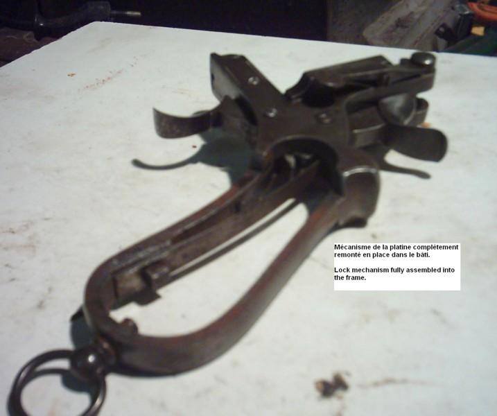
REASSEMBLING THE LOCK MECHANISM (pics 13 to 15)
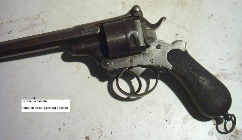
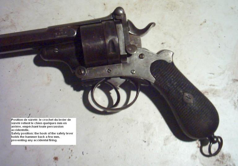
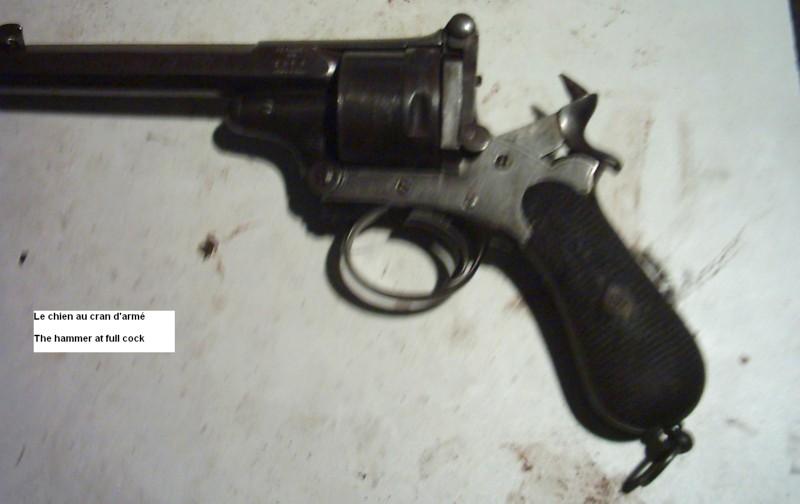
This operation is rapidly done, without any problem, and I can check the proper working of the whole lock mechanism. The pictures show the different possible positions of the hammer: resting/striking position, safety position and full cock.
Like on all Liège-made revolvers that include a cylinder locking cam integral to the trigger block, the empty cylinder can turn freely when the hammer is down or in safety position.
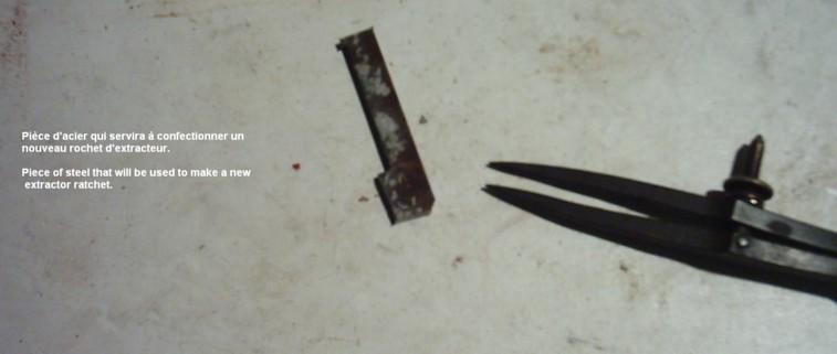
MAKING A REPLACEMENT EXTRACTOR RATCHET (pics 16 to 28)
Pic 16
Pic 17
Pic 18
Pic 19
Now that was a tough one.
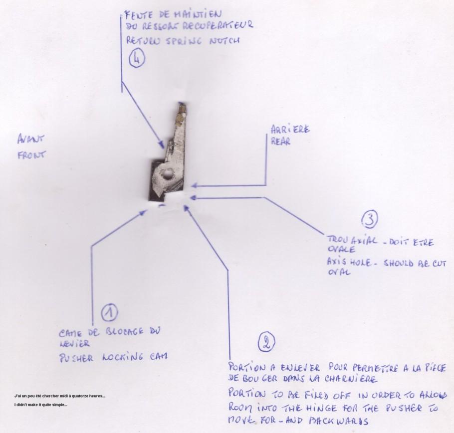
By the start I was absolutely sure that the system was identical to that of the Webley and Smith&Wesson topbreaks, consisting in a flat disk that moves into the hinge and that has a more or less long pin in its upper part, and a notch cut in its lower part, with an oval central hole in which a tiny return spring is fitted.
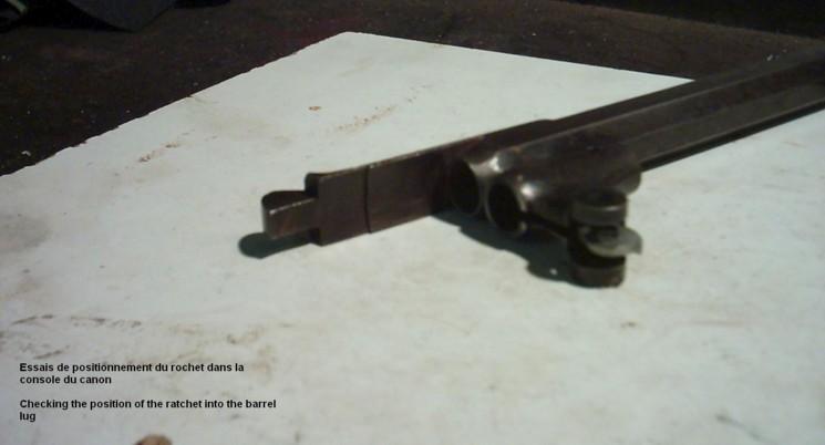
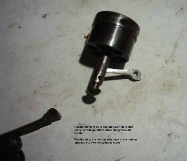
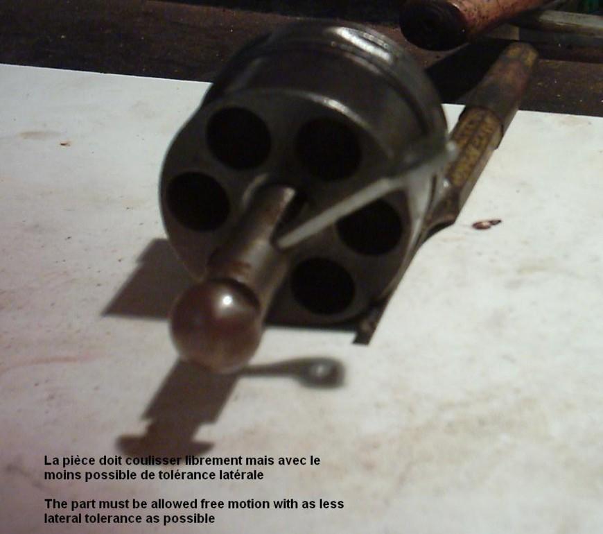
When the gun is being opened, the disk turns along with the hinge until the notch in its lower part comes to rest against the frame. As the opening motion is continued, the upper pin, the end of which enters the cylinder arbour through a lateral cut, pushes out the star extractor, expelling the empty shells. At the end of the opening motion, the barrel lug pushes the disk inwards, which causes the lower notch to disengage. Since the disk is now free again, it does not hold the star extractor in position anymore, so that the star is pushed back home by the pressure of it spring, allowing for reloading.
When the gun is being closed again, the small return spring in the oval hole of the disk pushes the latter back in its original position.
That system has become classical on the vast majority of the topbreak revolvers and is in fact relatively simple. It was originally specially designed for the cavalry, since reloading a revolver while sitting on the back of a running horse, is not easy.
Yet the system is impracticable unless the ejector star returns home after having expelled the empty shells, otherwise the protruding star would prevent reloading of the chambers. Some models include a small button or lever that pushes the disk inwards before the gun is opened, so that the extractor star does not come out and the loading can be checked without the risk of losing unfired cartridges.
Starting from the basic principle: opening-extraction-return home of the star, I was convinced that the Counet should feature a similar system, with as only difference a quite long upper pin, due to the general pattern of the barrel lug.
During the restoration works I was told that Counet had brought many changes and improvements to that and other models, so that I started thinking that he might have encountered difficulties with this opening system.
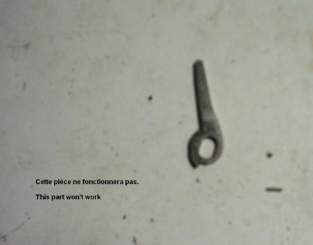
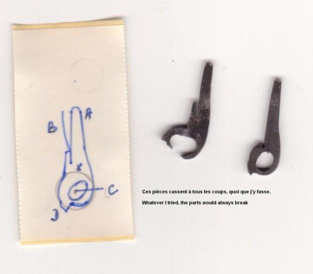
Whatever I did, each ratchet I made broke after one or two openings. I made four, each of them perfectly adapted, but they all broke (see pics 20a to 20e). I still don't understand why.
Pic 20a
Pic 20b
Pic 20c
Pic 20d
Pic 20e
That phase of the job was really discouraging, in the first place because I could not find out what was causing the problem.
One of our website friends provided me with a copy of the original Counet's patent drawings of 1871. These are simple drawings made by hand without any measurements, so they are not very precise; but they have been of great help though.
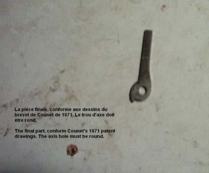
It took some time for me to realize that on these drawings, the central hole in the disk is round instead of oval, and that there is no return spring at all. That was confirmed a few days later when I had the opportunity to observe another Counet revolver, almost identical but manufactured by Francotte. On that gun too, the ratchet disk has a round hole and no spring, so it can not move inwards.
That second revolver showed me the way. As a matter of fact, Counet has solved the problem the opposite way.
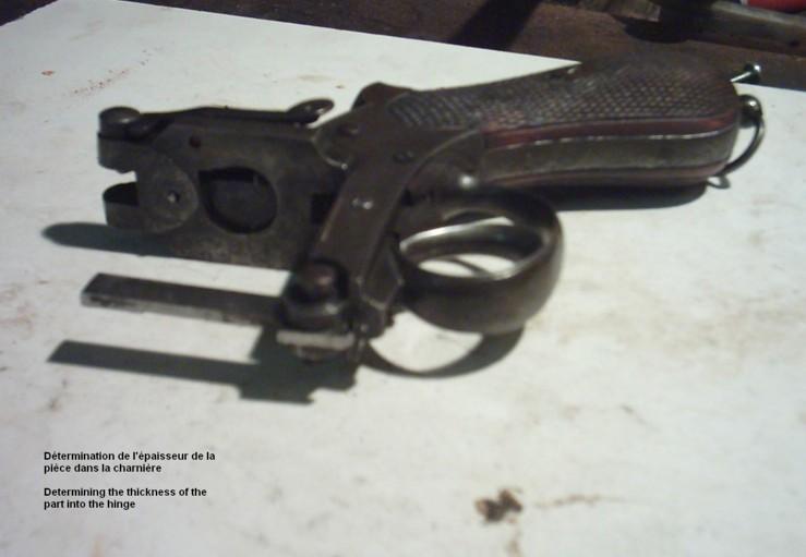
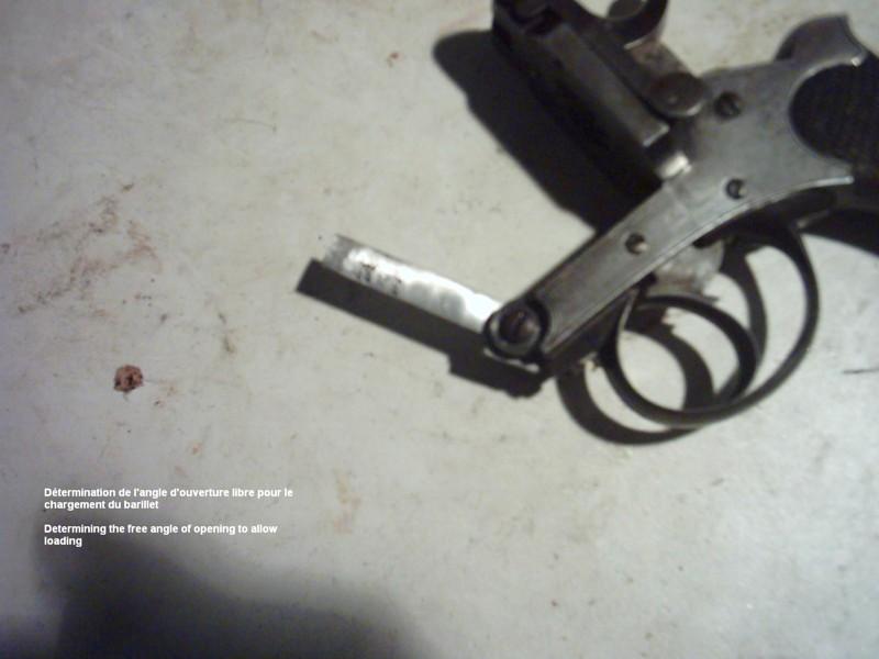
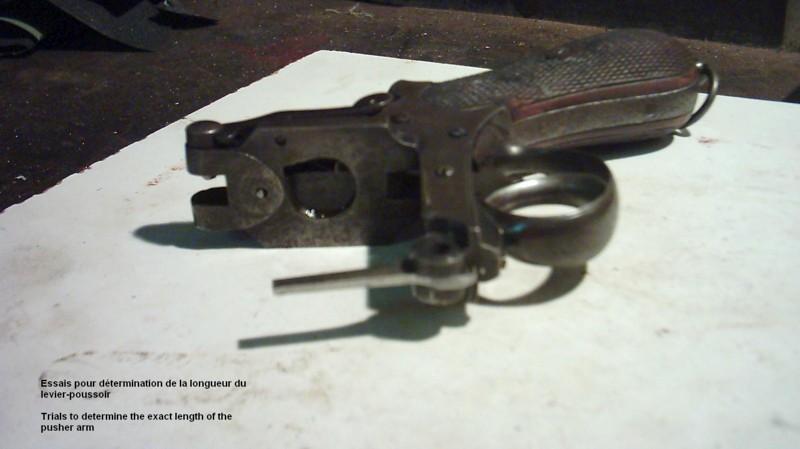
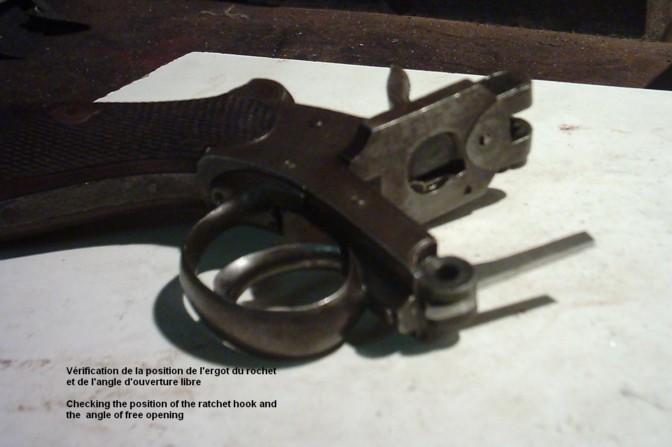
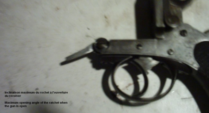
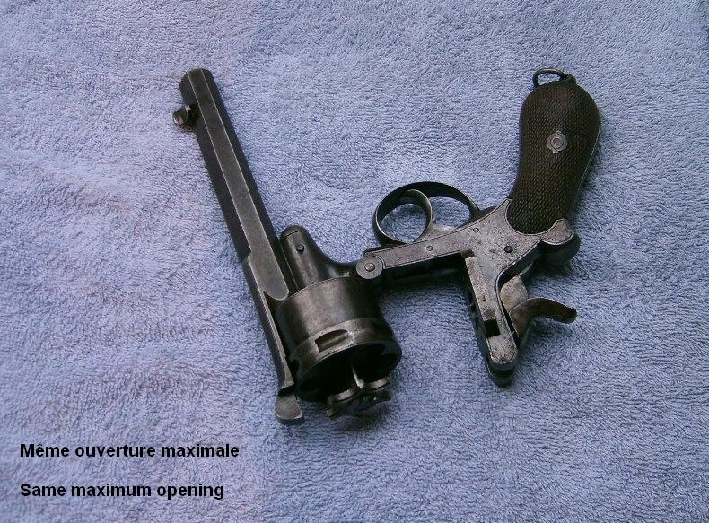
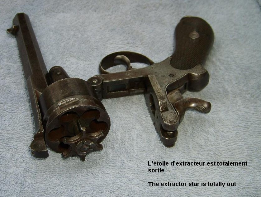
When the locking catch lever is depressed, the barrel falls open freely to an angle of about 45° before the extractor star starts coming out. When the barrel is pushed down all the way, the extractor star comes out all the way and expels the empty shells.
When the shooter then releases the barrel, it returns to the 45° angle under action of the extractor star spring, while the latter returns back home in the same motion.
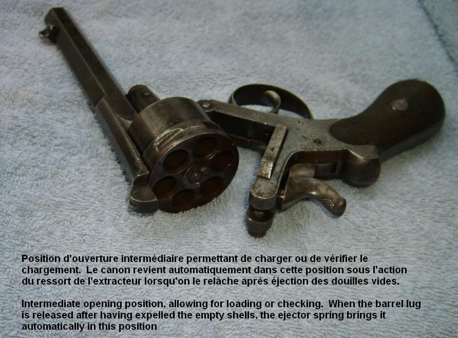
This 45° opening allows for an easy access to the chambers for reloading. A simple pressure on the locking catch lever causes the barrel to fall open, allowing for inspection or loading. If he wants to expel the shells, the shooter must push the barrel in the full open position.
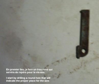
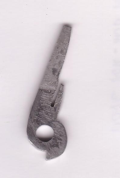
Having finally understood how the system works, I made a fifth ratchet, this time with a round central hole and a lower notch placed a little bit higher, and that was it.
It worked immediately without breaking, and the gun can be easily loaded and emptied as explained.
I won't forget that episode that has given me cold sweat but has also taught me allot about the different technical solutions the old day gunmakers developed to make their guns easy and fast to load and prevent incidents.
Although the classical system has proven its efficiency on almost all topbreak revolvers, I tend to think that the Counet system is even more reliable, because it eliminates more potential risks of jamming due to rust or dirt or breaking the small return spring, while allowing for an even fast extraction and reloading.
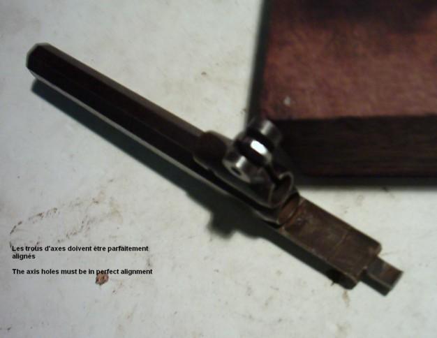
Pictures 16 to 27 speak for themselves: the only difficult part is to make a ratchet that fits perfectly into the hinge and pushes the extractor star out at the right moment.
Working step by step and correcting patiently the angles and the shape brought me finally to a good result.
Pic 21
Pic 22
Pic 23
Pic 24
Pic 25
Pic 26
Pic 27
I finished the job by tempering the disk to harden it, however at a lower temperature and cooling it directly in oil.
FINAL REASSEMBLY AND TRIALS (pics 28 to 33)
Pic 28
Pic 29
Pic 30
Pic 31
Pic 32
Pic 33
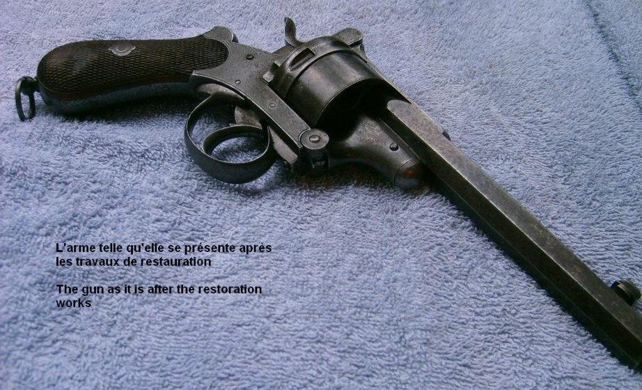
Reassembling the whole gun is easy, and what I have in my hands now is a very nice revolver. I really don't feel like returning it to its owner!!
It is a big and powerful military type revolver that can compete in quality with any other weapon of its time. It is perfectly finished in every detail.
Pictures 28 to 30 show it fully opened with the extractor out; pictures 32 and 33 show it in the loading position, and picture 31 show the weapon ready to be displayed as a witness of the skills of an almost forgotten, but also one of the best Liège gunmakers.
Marcel
And now, after the word of the Master, here are the images of the photographer after the work of restoration.
Alain