
THE 1926 BAYARD REVOLVER
The revolver shown here is one of those Liège productions that is said to have become very rare. According to some people, it has even become impossible to find. This is rather surprising, since we have found one that bears a 5-digit serial number (26XXX). To be honest however, I have to admit this is the first one I've seen in 40 years of collecting.
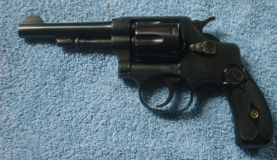
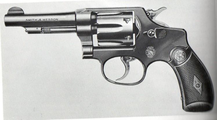
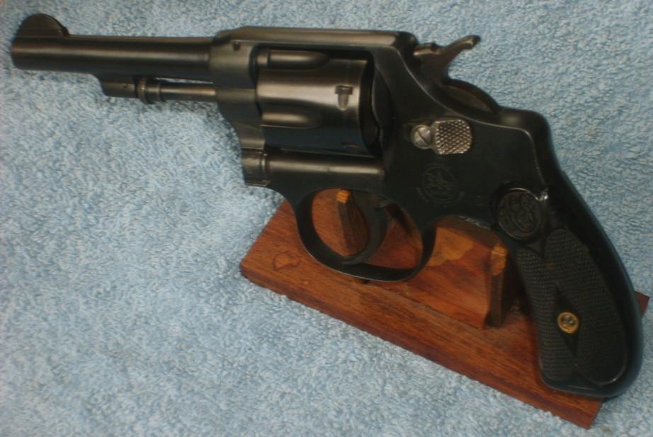
At first glance, one would identify this revolver as a Smith & Wesson Hand Ejector Second Model .32 of 1903, but it isn't.
This is a perfect clone, issued by the Anciens Etablissements Pieper Company of Liège, owner of the Bayard commercial brand, and including two patents granted to engineer Joseph Declaye.
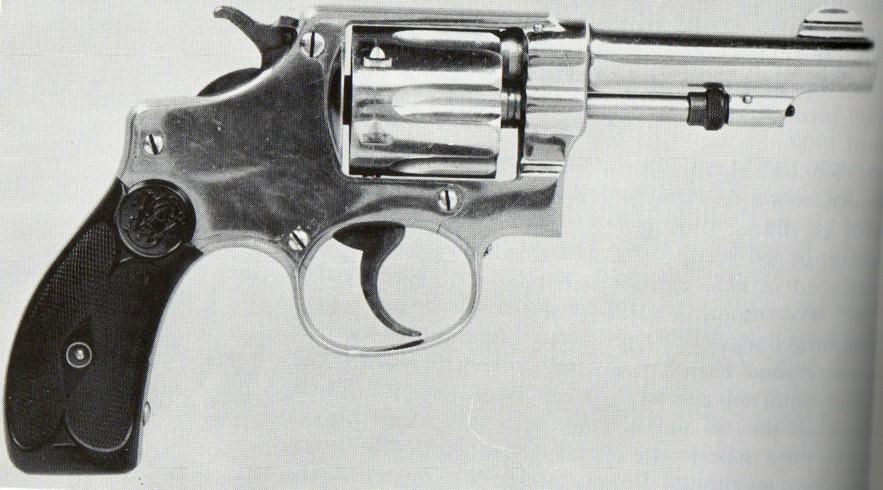
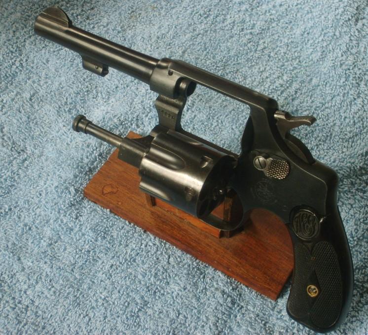
Except for the general pattern of one internal part and of course the markings, this revolver is in all respects absolutely identical to the abovementioned S&W, as comparison of pictures 1 and 2 with pictures 3 and 4 will show.
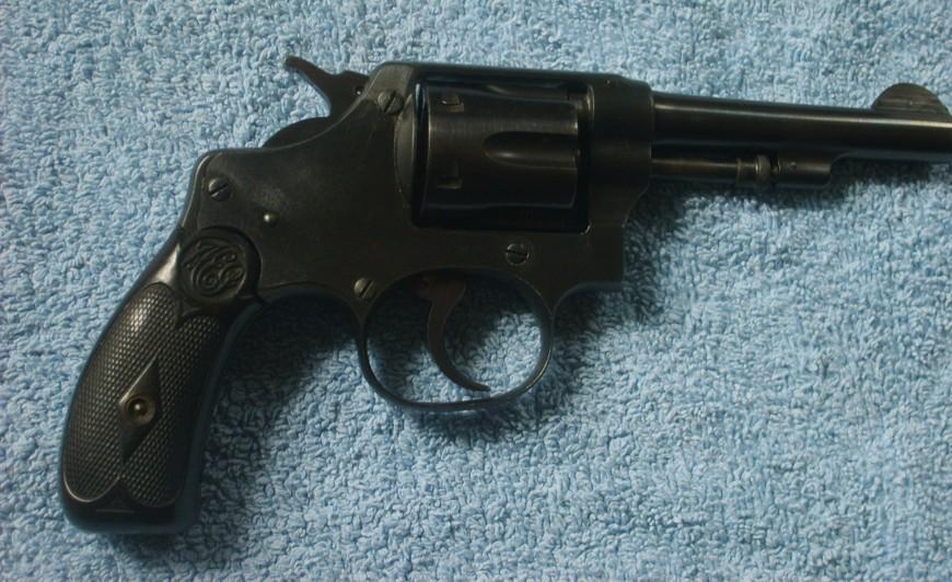
The Bayard is a "police size" six-shooter, chambered for the .32 Long S&W central fire cartridge. Like its American cousin, the revolver has a "reverse" lockwork, which is accessible from the right side. The cylinder swings out at the left side, but turns counterclockwise.
Empty shells are expelled by pressing the cylinder axis inwards, which causes the ejector star to push them out of the chambers (Hand Ejector).
The gun features three different safety devices which are explained in detail below. Those safeties prevent any risk of accidental firing:
- Rebound hammer
- Hammer locking cam
- Locking cam that blocks the whole lockwork when the cylinder is swung out.
The specimen I have on hand remains in an outstanding condition, almost mint, and has evidently never or very seldom been fired.
The left side of the frame bears the famous "Knight Bayard" logo and the medallion on top of the bakelite checkered grips show the maker's initials A.E.P. The Liège proofmarks are stamped on the rear face of the cylinder.
The finish is a nice satin dark blue, quite different from the inimitable Smith & Wesson "glossy blue", but therefore not less beautiful.
Only the cylinder unlock button at the left side of the frame, has been left in the white.
On the field of quality, adjusting and finish, the revolver equals its American example. The top quality can be seen from the doorstep.
By reception, I noticed however a few small mechanical problems:
- In the single action mode, the cylinder locking cam plunges down to release the cylinder, but doesn't come back up every time. This is hazardous since the cylinder could turn freely during firing.
- The trigger does not return very well, and is sometimes completely blocked.
- The hammer falls down but not far enough to strike the cartridge.
- The cover plate is not properly adjusted and closed.
Those minor fawls, unexpected on a weapon that has practically never been used, can only be the result of a skilless disassembling – and reassembling - by the usual village idiot.
Fact is that this revolver, if very easy to disassemble, is difficult to reassemble without some specific tools, and is quite delicate to tune.
It looks like I have to disassemble it completely in order to get it back in order.
PARTS LIST AND WORKING
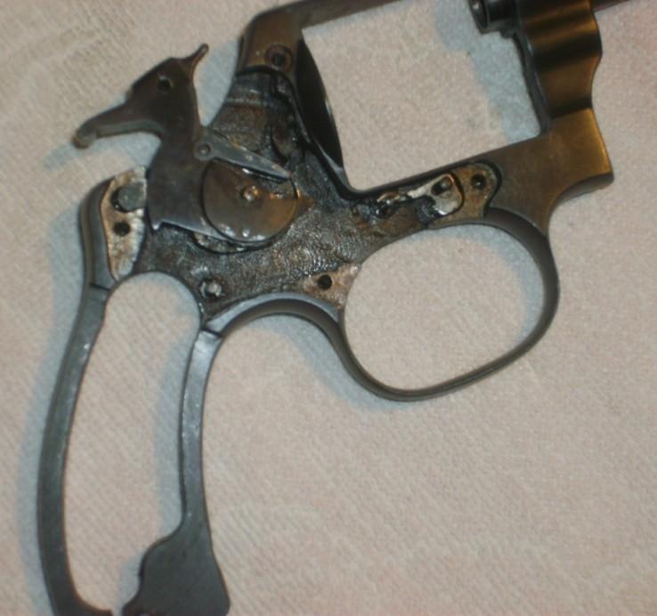
Picture 5 shows the gun fully stripped, except for the thumbpiece and the cylinder locking cam. In order to take off the latter, the trigger axis has to be disassembled; but as that axis is fixed in a hole drilled in the frame and held in place by a very tiny clip, I prefer to temper my temerity.
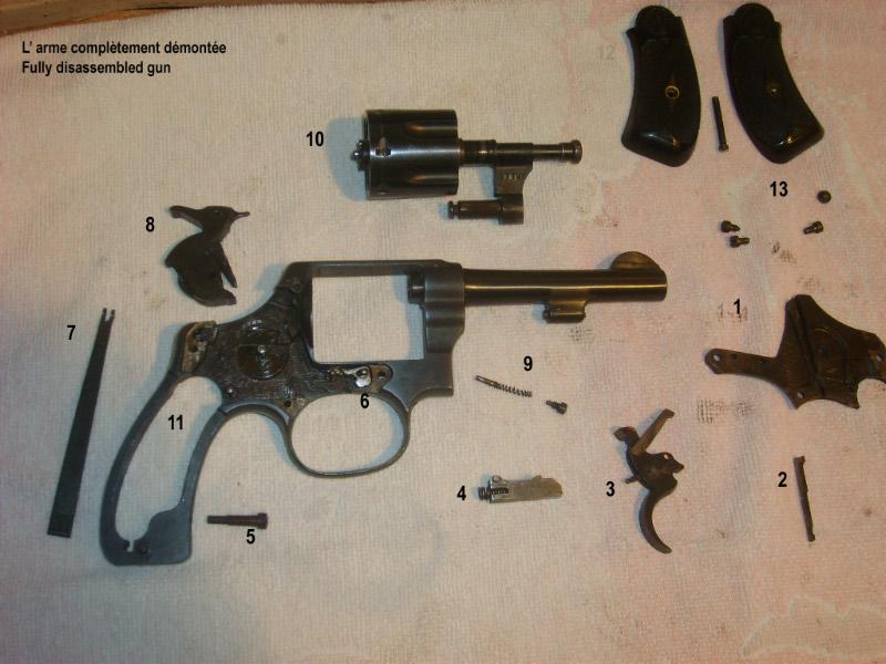
1. Cover plate with hammer cam slide and triangular lever
2. Hammer locking cam (only part that has a different shape than the S&W one)
3. Trigger with mounted hand and visible articulated lever at the rear
4. Trigger/rebound slide with the trigger return spring
5. Main spring strain screw
6. Cylinder locking cam
7. Main spring
8. Hammer with sear and stirrup still in place
9. Cylinder locking cam spring with screw and center pin
10. Cylinder and cylinder lug
11. Frame
12. Grip plates and screw
13. Cover plate screws. The forward screw, located near the locking cam, holds the cylinder lug in place in the frame by protruding into the channel cut at the end of the latter.
Picture 6 shows the cylinder locking cam spring together with its center pin (1). That spring slides into an oblique channel drilled in the frame above the trigger guard (3) and pushes the cam upwards. The spring itself is held in place by a small screw (2) which is accessible from the outside, so the spring can easily be replaced without disassembling the weapon. Its strain can also lightly be modified by turning the screw very lightly in or out.
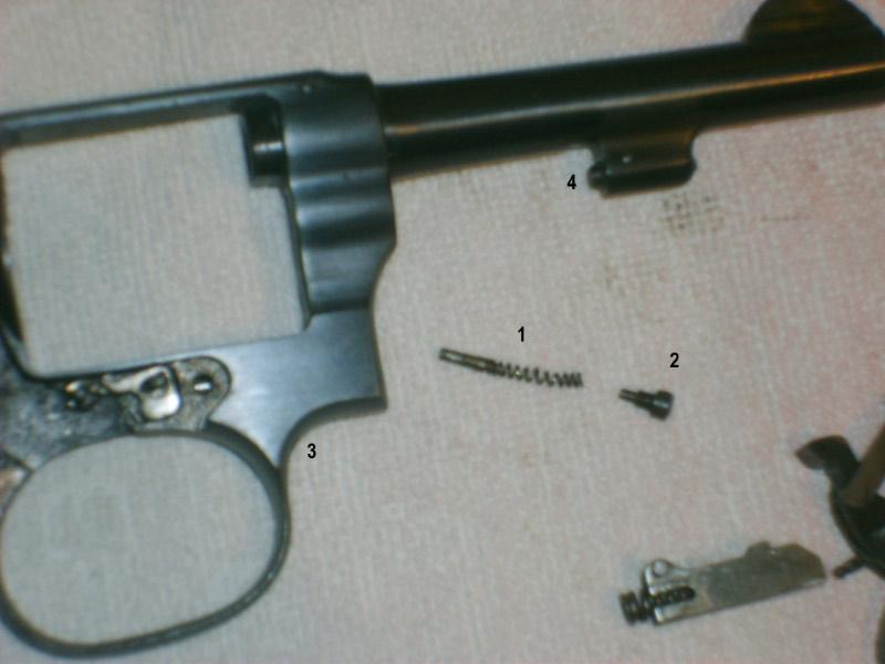
(4) Shows the spring loaded locking bolt that helps keeping the cylinder in place (see note in fine).
Picture 7 shows the detail of the trigger mechanism and its approximate position in the lock. The trigger has a small round headed articulated lever at the backside; the rounded end engages a small round hole cut into the forward end of the rebound slide.
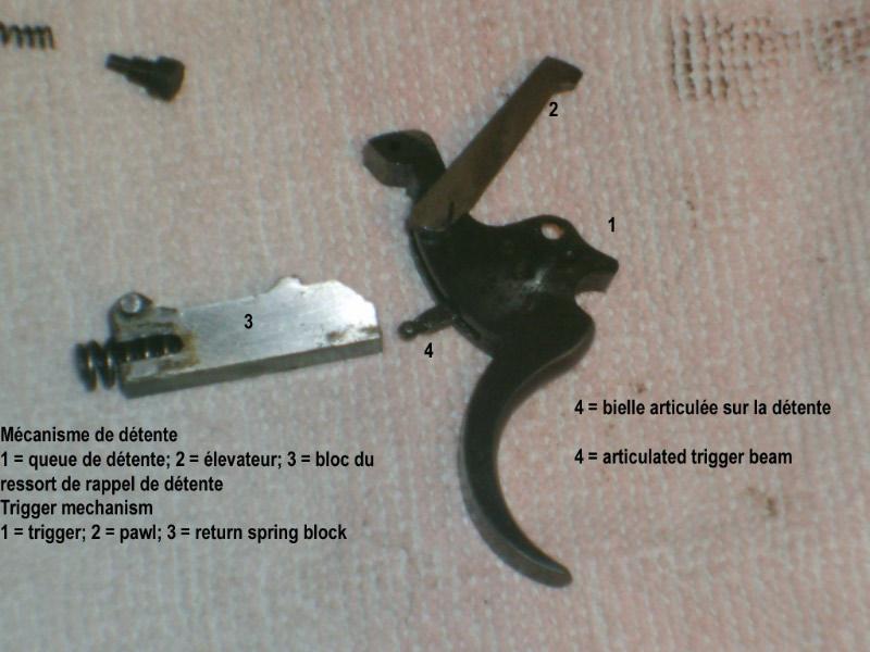
The slide contains the trigger return spring, which rests against a pin fixed into the frame. The small protruding pin at the back right side of the slide engages the hammer locking cam lever, while the round upper part causes the hammer to move back when the trigger is released (rebound hammer).
The hand or pawl is shown mounted in place on the trigger. The hand is pushed forward by a thin flat spring located in the trigger body.
In order to mount the hand in place, that spring must be pushed downwards with a small screwdriver. The spring is accessible on the upper part of the trigger once the latter has been mounted in place.
Picture 8 shows the bolt which is connected to the thumbpiece. The forward part of the bolt has a cylindrical shaped cam which meets the cylinder pin and holds it in place; the rear part has a locking cam over the whole thickness of the grip frame.
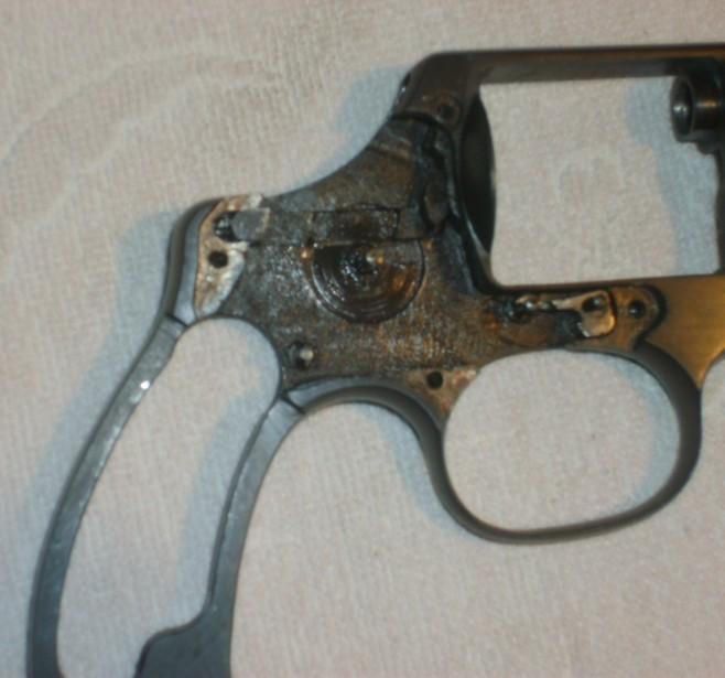
When the thumb piece is pushed forward, the cylindrical cam moves forward and pushes the cylinder pin out of its home, enabling the user to swing out the cylinder. Because of the locking bolt under the barrel, the user has to use both hands to open the cylinder. It cannot be swung out by a rapid wrist movement like on a Colt.
Once the cylinder swung out, the bolt is pushed forward by its spring.
That movement causes the rear cam to move forward under the hammer rear profile, which blocks the hammer into the resting position and locks the entire mechanism, so that it can't be cocked as long as the cylinder is not pushed back in place.
For the same reason, the cylinder cannot be swung out when the hammer is cocked, since the round part at its back keeps the bolt cam home and blocks the thumbpiece.
Picture 9 shows the position of the bolt cam with the hammer cocked and the cylinder back in place: the cylinder pin pushes back the bolt and the rear cam is driven back home, enabling hammer movements.
Picture 10 shows the cover plate's internal side, including the hammer locking cam channel. Also visible in (1) is the small triangular lever that is connected to the cam through a notch cut into its lower part, and activated by the rebound slide.
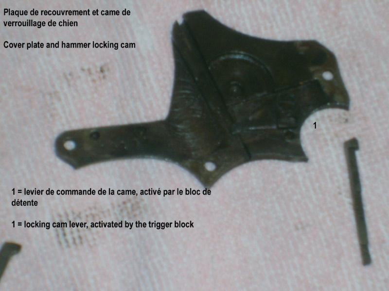
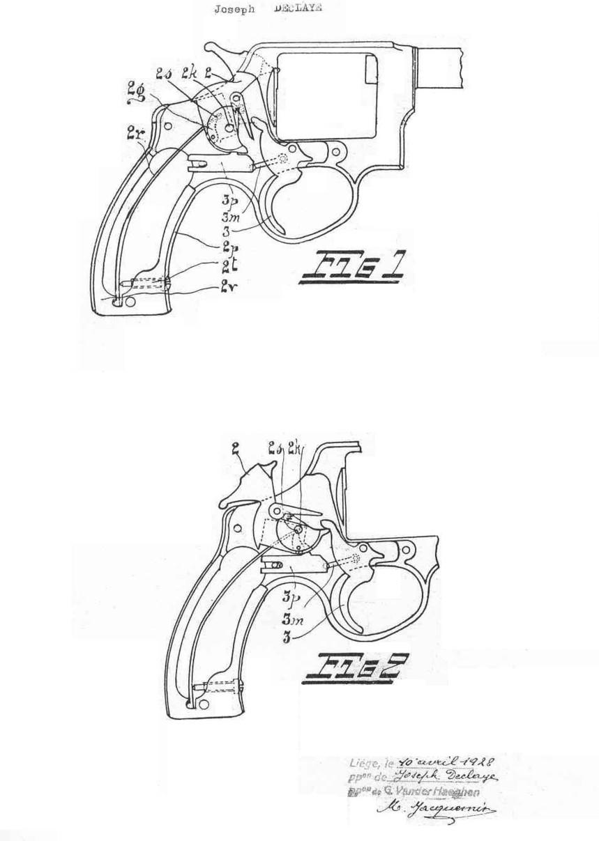
Fig 1 to 4 on the patent drawings (pt) show clearly how the system works:
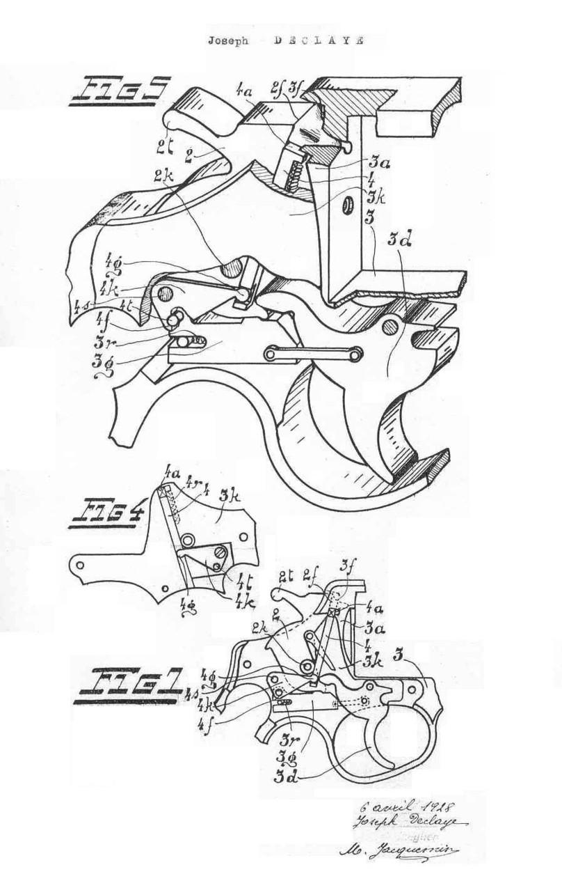
- In the double action mode, the depressed trigger moves back around its pin; the back nose engages the sear and pushes it upwards until the hammer escapes and falls down to strike.
- In the single action mode, when the hammer is thumb cocked, its lower part engages the trigger nose and pulls it upwards.
In both modes, the forward part of the trigger pushes the locking cam away for a fraction of a second so that the cylinder is unlocked and can turn. Then the locking cam is pushed back upwards by its spring and engages automatically the next notch, locking the cylinder in place with the next chamber in alignment with the barrel.
In the same movement, the lever at the rear of the trigger pushes back the rebound slide, which comprimes the return spring against its pin in the frame. The rearward movement of the slide causes the triangular lever to move downwards, which causes the hammer locking cam to move down and clear the percussion hole. The hammer can strike the cartridge.
When the trigger is released, the trigger return spring pushes the slide back forward and brings the trigger back in place. The rounded upper part of the slide pushes on the rear bottom part of the hammer, which pulls the firing pin a few mm backwards, while the triangular lever pushes up the hammer locking cam. The cam head moves upwards right in front of the hammer in the percussion hole, blocking the hammer and preventing any accidental strike, while the gun can be immediately fired at will in both modes.
Very efficient safety; the hammer locking cam is slightly different from that of the S&W, but it has the same function.
As previously said, the reassembling is a quite delicate operation, especially the trigger mechanism. The trigger must be mounted in place
first; and mounting the return slide without proper tools to keep the spring compressed is a difficult operation because the spring must be held firmly and the trigger lever placed in the right position in order not to break.
The cylinder cam spring has to be perfectly straight in order not to jam in its channel.
The main spring is easy to mount in place, but its strain that can be adjusted by the small spring at the bottom of the grip must be in accordance with that of the return spring, otherwise the trigger won't return normally.
Finally, the most delicate part is the placement of the cover plate with proper alignment of the triangular lever and the hammer locking cam.
One must make sure that all parts are perfectly in alignment so that the triangular lever can engage the small pin on the rebound slide; otherwise the whole mechanism will jam. I guess the village idiot has found out and knows exactly what I mean.
At last, the cylinder is placed back and held by the cover plate forward screw, and the grip plates.
A very nice pocket revolver, very well made and quite powerful with its .32 Long S&W cartridge (Pictures 11 and 12).
Some may say that "it is only a copy"; but like the Chinese, I would say that if a cheap and untrue copy is an insult, a perfect clone is a homage to someone else's skills.
NOTE
When the first revolvers with swing-out cylinders were issued, the American Ordnance officers had demanded the cylinders to turn counterclockwise. The reason for that decision, which forced Colt and S&W to adapt and replace some of their machines, has remained unknown to this day. However, many authors tend to think that the reason lays more in the vanity of officers who wanted to leave their personal mark in history, rather than in the technique of arms making. If those people were indeed seeking notoriety, they can sleep on both ears, for today, more than one century later; their fame as incompetent idiots is still untamed.
Both S&W and Colt had declared that the cylinder rotation not only had no influence whatsoever on the gun performances, but moreover, the reversed lockwork tended to push the cylinder out during the firing, because it was still swinging out at the left side. Since the Ordnance officers would not accept this argumentation, the makers had to face a new technical problem. S&W solved it by adding the spring loaded bolt under the barrel to help prevent the cylinder to swing out. The position an strain of the bolt can be adjusted by turning the cylinder pin head.
On their next models, both makers returned to the classical system without asking permission to the Ordnance officers.
With thanks to:
Alain Daubresse (Alantrigger), webmaster of Littlegun and owner of this little jewel;
Guy Gadisseur (GG) for the historical details regarding the Liège makers;
Michel Druart for the patent drawings and details.
Marcel